Lego Action
As a child I didn't have Lego in my toy box. I started using Lego just prior to 2000, using 2x4 bricks and roof tiles to build ramps and walls. Within the last 7 years I have expanded my Lego usage to include a variety of sets and elements. My favorite themes include: Classic (assorted parts), City, Technic, and Friends. While I like many of the Lego sets, I often either build modified versions of them or just use the parts to build something different.
Building a Lego model that sits on the table looking pretty is a good thing. But adding motion, lights, and sounds to it takes it to a higher level of fun and realism. I call this "Lego Action" and will refer to that using "LA" for this page.
Lego themes for LA
Lego has given us some great tools to help with LA. Modern tools are mostly controlled by an 'application' (called "app" in this document) which is run on a 'smart device' (tablet or phone) which meets certain operational requirements (such as Bluetooth and Location ability). Here is a brief list of Lego themes offering LA ability:

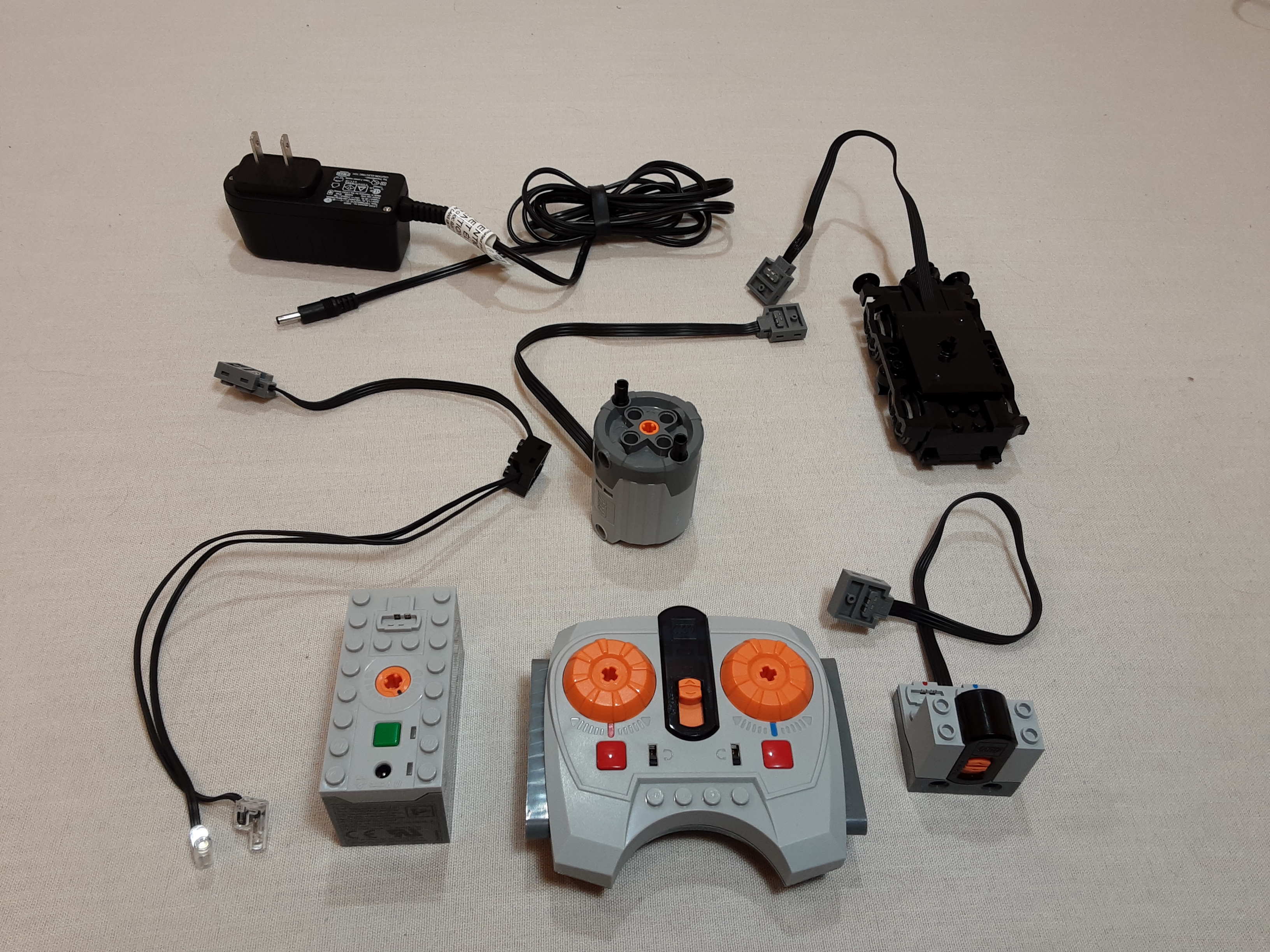
-
Mindstorm (1998)
Operated by: Coding
Not shown -
Power Functions (2007)
Operated by: Remote
Upper left -
Boost (2017)
Operated by: Coding
Upper right -
Powered Up 4-port hub (2018)
Operated by: Coding
Lower left -
Powered Up 2-port hub (2018)
Operated by: Coding or remote
Lower right -
PoweredUp app (2018)
Operated by: Coding
Not shown -
Control+ app (2019)
Operated by: Coding
Not shown
I am going to quickly cover the basics of each system so you get an idea of what it does best. There are many sites which already cover more detail about each system so I won't repeat the specifications here. This article is based upon MY PERSONAL EXPERIENCE and some information which Lego has. Different setups often produce different results so some things may work a bit different for you.
It is worth noting though that no matter which system is used to add action, you can still use any Lego elements to build the model. Most mounting in the modern systems is via 'Technic' connections, but there are many elements which convert those to stud (classic) style mounting. Model design will need to take into consideration the size of the hub/devices used as well as the wiring path between them. The hubs (any non Power Functions systems) have the battery compartment within, so there is no additional battery pack. However, since the batteries are in the hub, model design should allow easy access to the battery panel for changing batteries.
In the same respect, existing models built using the old 'Power Functions' system can be modified to use the newer 'Boost' or 'Powered Up' systems. The amount of modification depends on the size and mounting differences between the old and new devices. The 'Boost' Move Hub is the largest of the hubs, so it needs more room in a model. In contrast the 2-port 'Powered Up' hub is similar in size to the small 'Power Functions' battery packs, so it should fit well AND it doesn't require the IR receiver so extra room is gained there.
Mindstorm
To be honest I have never investigated the Lego Mindstorm system. So this section is short only because I know almost nothing about it.
Mindstorms was mostly an educational tool, not truly a 'toy' in that respect. Some people use Mindstorm devices to add LA to their own models, but it is still used more commonly for education in schools and FLL (First Lego League) competitions.
There are 4 generations of Lego Mindstorms:
Robotics Invention System (1998)
Mindstorms NXT (2006)
Mindstorms EV3 (2013)
The WeDo system branched from Mindstorms
The earliest of these systems devices were actually 'tethered' to a computer (wires connected the computer and the model). Then "intelligent bricks" were developed with processors in the devices themselves to allow for portability. This was the foundation for the systems being introduced in todays modern times.
Power Functions
The Lego "Power Functions" (PF) system was launched in 2007. Although it is no longer available from Lego, devices can still be purchased from people selling theirs. Unlike the Mindstorm system, PF has no computer relations. It is a basic system of motors and lights attached to a battery box and controlled by a handheld IR remote and an IR receiver. Because of the simple to use nature and a fairly compact design, it was easy to add to a model. Rechargeable battery boxes exist to reduce battery costs/disposal, but several varieties of normal battery packs also exist.
The remote/receiver has two device ports, red or blue. There are 4 channels available so that up to 4 different red/blue port pairs could be controlled with one remote. Devices could be mixed as desired, two motors, two lights, or one of each. The speed of a motor or intensity of a light could be controlled with the remote.
PF uses 'stackable' connectors, meaning more than one device could be attached to a red or blue port. However, all devices on a port would have the same behavior as the others (speed or intensity). This made it possible to chain many lights to just one port.
The PF system is great for remote control of trains, vehicles, or any simple LA expansion of a model. The biggest drawback is that only 2 ports (red/blue) exist on each channel. So if two motors are used (1 for speed and 1 for steering), adding lights is not possible. PF is ideal for trains since they have no need for steering.
With PF, there are no apps to install and no 'screen time' required. So although coding is not an option, the features needed to operate simple models is all done with a simple handheld remote control!
Boost
The Lego "Boost" system came out in 2017 and is still fairly well supported today. It features a 'Move Hub' with 2 internal motors and a tilt sensor, an external motor, and a color/distance sensor. Boost models were built around the Move Hub and showcased the abilities of the hub and some clever building techniques. Boost models are controllable ONLY by coding via the Boost App, not remote control. The Hub connects with the app via Bluetooth, so it may not be available for older computer devices. Boost is NOT compatible with Power Functions devices.
The system has several models that can be built with parts in the set. The instructions lead the builder through steps to construct the models AND teach coding along the way. Each time a model segment is built, the focus turns to how to program it in the app. This helps the builder to understand the relationship to the model segment and the code blocks available to give it action. While the included models may yield a lot of fun themselves, the app includes an 'open code' area. Custom code can be created using any of the defined code blocks available.
The Move Hub also has a status light. This indicates power and Bluetooth connection status. It is also possible to change the light using code blocks. The app has a sound clip library which can be accessed with code blocks and it is also possible to record custom sounds. All sounds are played on the device which runs the Boost App. The light and sound ability add more possibility for LA in a model.
Although Boost is an expensive set, it offers a lot of models and the ability to expand into custom models. I was impressed by the way coding is taught during construction and found it to be a very productive teaching method. The visual coding manner can be enjoyable for those who can grasp basic logic and functional processes.
The Boost hub and coding system allows custom models to be created and controlled with a great deal of flexibility. The 2 internal motors allow for motion without having to use external wired motors. The color/distance sensor opens up a lot of options for detection of objects and movement. The timing and logical code blocks give the ability to synchronize or delay activity. All of this and more gives a large amount of control to how a model can be put into motion.
The biggest drawback to Boost is that battery access requires opening a large panel at the bottom of the Move Hub. So if any of this area is covered by your model, it has to be taken apart to change batteries. I would have loved it more if Lego had included a method for adapter to simply plug in to recharge rechargeable batteries, that would have made the battery panel space more usable also.
Powered Up

In 2018, Lego launched their "Powered Up" (PU) system. This is basically a combination of Power Functions devices and Boost style Bluetooth/App coding control of them. As this is a new system, it is NOT compatible with Power Functions devices and some PU devices may not be compatible with Boost.
The Hub is the foundation of the PU system. This hub is the battery box and the Bluetooth receiver to get commands from the app. Unlike Boost, the hub has no internal motors although it does have an internal tilt sensor. Either hub can accept devices which include motors, lights, and sensors. The motors and lights are similar to their Power Functions cousins in operation but PF devices are not compatible with PU due to the different connectors.
In my limited testing so far, the Powered Up app seems to be able to allow open code access to control the 2-port hub, 4-port hub, and Boost hub. But only the first hub on the list gets controlled, you can change the device order within the app to switch which hub is currently 'active'.
The PU app is similar to the Boost app in some respect. If you learned coding using Boost, you will be able to transition to PU easily. The PU app has sections for the Lego PU themed models and also an ability to create code for custom models. PU code blocks reflect commands for the PU supported devices and the sound library has different sounds than the Boost app has.
Where Power Functions relied on a remote control to send commands, PU relies on using the app installed on a 'smart device' (tablet, laptop, phone) which meets certain requirements. Bluetooth is used as the communications protocol between the app and the PU hub. When a program is run (invoked) on the app, it sends the commands to the appropriate devices connected to the hub. While this system was really designed to be controlled mainly by the app, it does support creation of code to allow use of the remote control.
The Hubs have several mounting points for Technic connectors. Models can be built around the hub as desired. Remember to keep the area around the battery access panel free so the model doesn't have to be taken apart when changing batteries. The hub status light can be changed using code blocks and programs can make decisions based upon the orientation of the hub according to its 'tilt' position on X/Y/Z planes.
The app also offers code blocks which report the tilt position (X and Y only) of the device running the app. This makes it possible to control actions based upon the device orientation. Thus the device CAN be used as a type of remote control. For example, tilting it forward/backward could add/reduce vehicle speed and tilting it left/right could steer a vehicle in that direction.
Although Power Functions devices are not compatible with the PU system, there is a code block in the Powered Up app which allows the color/distance sensor to send IR signals to a Power Function remote receiver. This is a great concept for 'backwards compatibility' with Power Functions models. This greatly expands the ability to control more models with the same app for those of us who have many Power Functions devices and models.
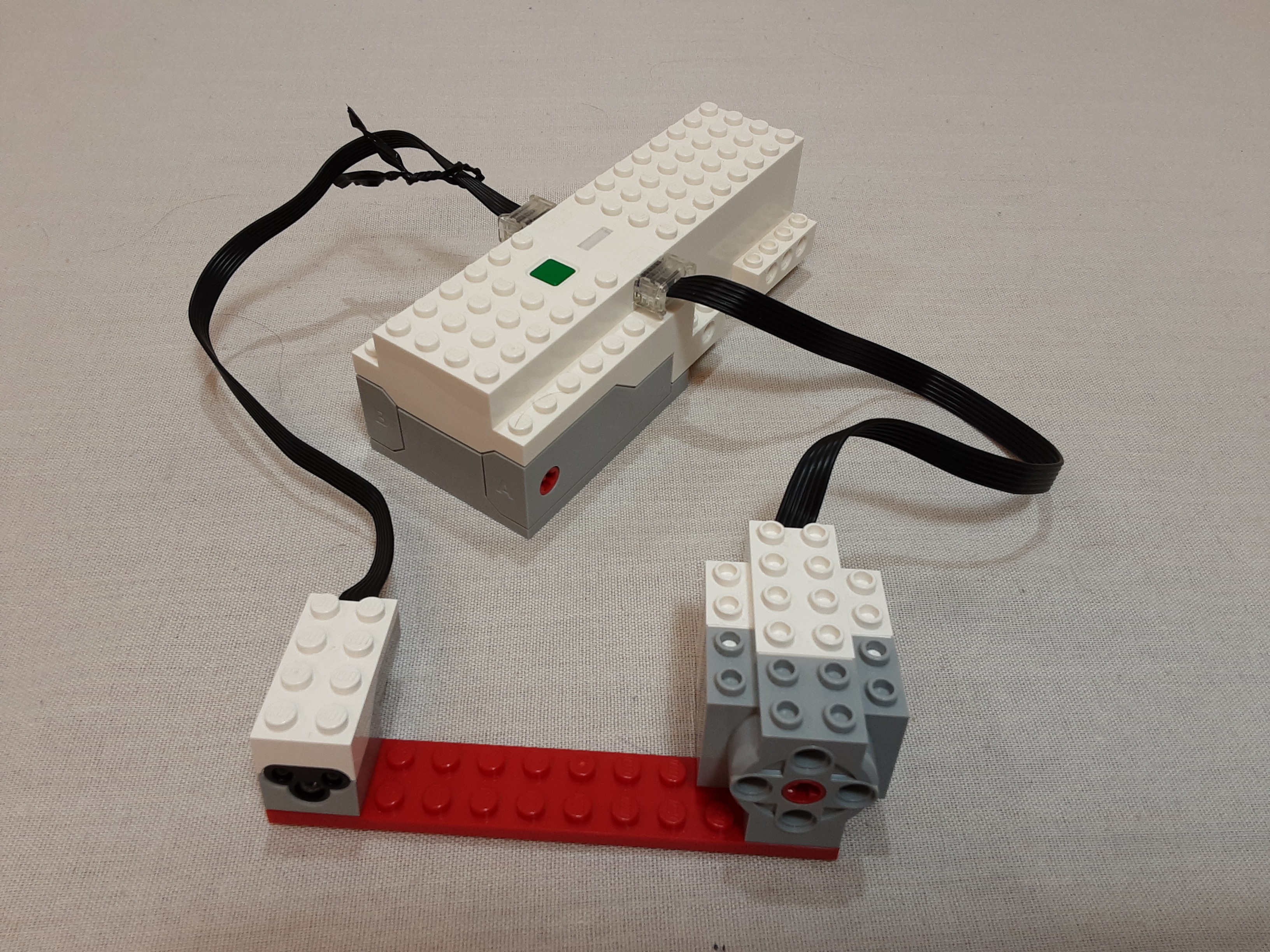
2-port hub:
The smaller size of the hub allows for smaller models to be created. The hubs lighter weight provides for less impact on the movement of the model. Remote operation allows models to run without using a 'smart device' to run the app, so they can be truly portable but without any sound effects provided by use of the app.
This hub uses the classic 'stud' style mounting. It has no 'Technic' connection ability, except by using elements which can convert to it. This makes some sense though as smaller models tend to be built using classic elements while larger models use more 'Technic' elements.
The biggest drawback of the 2-port hub is that it only has 2 ports, which limits what devices can be attached to it. But considering the use is to simply control vehicle speed and steering, this isn't much of a drawback. So basically if you want a simple vehicle setup that can be controlled by a remote, use the 2-port hub. If you need more, use the 4-port hub.
4-port hub:
Having 4 ports increases the flexibility of uses in models. Vehicles could have 1 motor for speed, 1 motor for steering, 1 set of lights, and 1 sensor for monitoring objects. Thus a full featured vehicle is possible under app control, but not under remote control. Models could make use of two sets of sensor/motor combinations to provide for different movement based upon surrounding conditions.
This hub uses only 'Technic' style mounting. Its heavier weight will need to be supported well in the model framework. Having this hub near the center of the model will allow for more evenly distributed wiring lengths to devices AND detour imbalance due to uneven weight distribution. While having this hub near the bottom/center of the model may help keep battery panel access handy, it may also cause problems in keeping the power button, status light, and ports accessible. Depending on the model, some creative design might need to take place in order to meet these challenges.
PoweredUp app:
In 2018 Lego introduced the "PoweredUp" (PU) app which is part of the Powered Up system. The PU app is geared more toward the control of certain Lego models. But it also supports open coding for custom models in the "CREATE" area.
Control + app:
In 2019 Lego introduced the "Control +" (C+) app which is part of the Powered Up system. The C+ app is geared more toward vehicle control. It appears that the C+ app only works for those Lego models designated with the C+ theme. In other words, no open coding for custom models.
Notes:
The device compatibility between Boost/PU/C+ varies by device. Each system has a specific app to control the associated devices. I haven't done much inter-system testing to make any useful conclusions yet. My best advice is to check with Lego prior to purchasing a system to determine how compatible it is with any currently owned system you may have. However, I have noticed that as of this writing the Powered Up app at least recognizes multiple devices (Boost hub, 2-port hub, 4-port hub, and remote) are present when powered on. So if the goal is to program custom models, the Powered Up app seems to be the best tool for the job.
Although the coding process seems to be similar between the different systems, I know of no way to transfer a project between different system apps. However, exact or similar code can likely be created manually as desired. Code blocks vary by app and with supported devices so some variation in code may be needed to perform similar functionality. It also seems that sound clips are much different between apps and I know of no way to import/export these between apps. So whatever app is being used determines what sounds are available.
There has been much online discussion about PU/C+ lack of 'stacking' devices like the Power Functions system allowed. However, this is more a limitation of Bluetooth operation rather than poor design by Lego. Power functions connections simply supplied variable power to devices, not specific commands. In contrast, Bluetooth devices are referenced by a 'device address', which is tied to the PORT which they are connected to. This allows precision in sending specific commands to specific devices on specific ports. Thus, multiple devices on one port (aka 'stacking') is not possible for Bluetooth communications.
For many years there has been a market for 'Third party' (non-Lego) devices/apps to provide LA solutions for custom model creation. These include lighting, sound, and 'smart brick' coding systems. There are pros and cons to pretty much any system available. So my best advice is to look around and use whatever meets YOUR specific needs best. Lego has been continually improving both app features and device firmware (although often slower than some people like), so don't give up on Lego just because something you want isn't in place quite yet.
Beyond vehicles:
Vehicles and trains are very popular models to build with Lego. Being able to build an RC car or run a train layout is indeed fun. But there is much more that can be done with the LA options of the systems discussed above!
Motors spin, which is what turns the wheels of vehicles or trains. But this same circular motion can be used to operate amusement rides such as a carousel or ferris wheel. Timing code blocks could even be used to automate the length of the ride and a delay for unload/load between rides. Or build a small circular photo cube or display case which rotates. This could be activiated by motion by using a color/distance sensor to detect movement nearby.
Lego makes 'tread/track' elements (as used for wheels on tanks or heavy construction equipment). Some of these allow for connection of elements on the front facing. I used this to create a Waterfall model for display. The motor ran the tread loop vertically and the treads had various bluish colored tiles on it to simulate water. The effect was close to watching a real waterfall. This same concept could be run horizontally to mimic a conveyor belt.
Motors do not have to just spin constantly either. Using the 'tacho motors' which are part of the Boost and Powered Up system, precise control over the speed, distance, and position is possible. As pictured above, I created an automated railroad crossing guard for a train display. A sensor detected the motion of the train which activated the program. The motor turned the crossing guard arm 90 degrees to lower it, then waited for a period of time, and then turned the motor 90 degrees in reverse to raise the guard. This is still a very simple example of what can be done.
Some elements can transform the circular motor motion to a more linear motion. A horizontal track can be constructed to have a model go back and forth in front of background scenery, such as shown above. Here the circular motor motion is changed into linear motion by using the toothed bars. These are mounted on a sliding platform, so whatever is on the platform (the dog) moves back and forth. The dog starts by its owner. Slowly the dog is pulled toward the other person, notice the hub light is red during this. Just before the dog reaches the person, it more quickly runs back to its owner (with green hub light). So the motor reverse speed is greater than the forward speed but the distance it travels (rotates) is the same (just opposite directions).
The main parts used for the sliding platform with their 'Design #' are: #3743 toothed bar, #4510 slide bar, and #2653 grooved brick.
This same action could be done vertically. This is how some elevators or esculator work so these would be possible to build and control. With a bit of creative coding and timing, an elevator could be made to randomly travel to different floors, stopping for a bit to simulate unload/load, and then continue. It could also be triggered by motion using a sensor. Many other cool ideas could be created using similar movements.
This shows one way to control a motor using the Powered Up app. Here the speed of the motor is controlled by the distance an object is from the sensor. The closer the object is, the faster the motor turns.
Notice the code being run here. This is a simple continuous loop which sets the speed of the motor (connected to port A) based upon the reported distance of the sensor (connected to port C). The motor speed is between 0 (off) and 100 (full speed) and the sensor reports distance between 0 (close) and 10 (far). So we subtract the sensor value from 10 and multiply that result by 10, giving us 0=far (motor off) to 100=close (motor full speed). If you want the motor to DECREASE speed as the object gets closer (such as for slowing a vehicle before a collision), just use the sensor value directly (without subtracting it from 10) before the multiplication by 10.
Notice I also have the code blocks for sensor reporting at the lower left of the tablet. You can watch the values for distance, color, and level as reported by the sensor. Note that color perception is only reliable when the object is very close to the sensor while distance and motion detection has a much longer range. Knowing the characteristics of the devices helps create models and code that work the way you want them to work. Experimentation is a key part of learning!
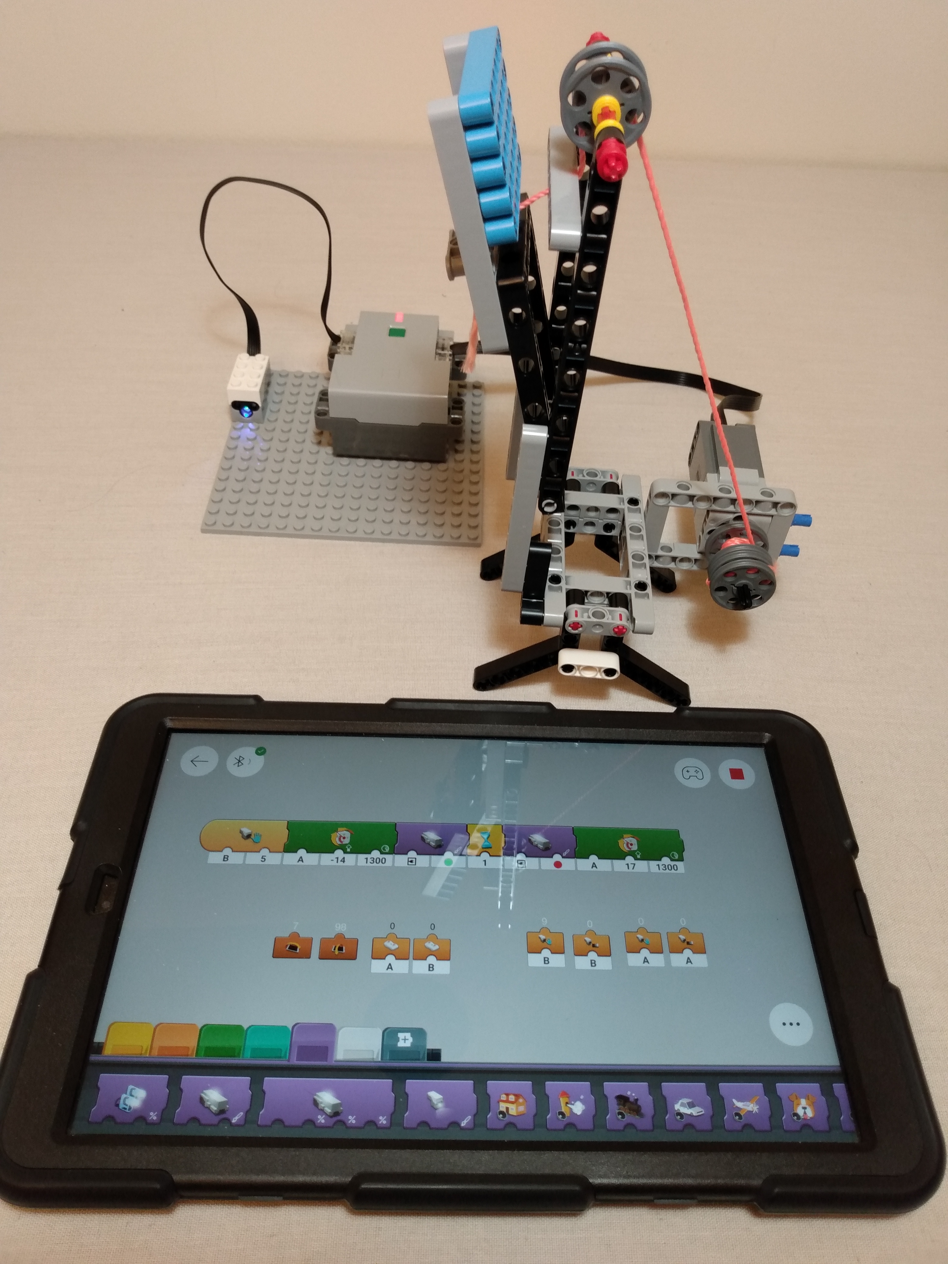
Motors can also be used to pull cables through a pulley system, such as how cranes work. Using twine or string (or any similar material) wound around a drum connected to a motor would allow a pulley system to do a variety of tasks. This could lower/raise a drawbridge for a castle or raise/lower a roadway over a river to let tall ships go through. Even a zipline could be simulated with this type of setup.
In the video above, a simple drawbridge is controlled by the Powered Up system. A string is connected to the bridge and runs though a pulley on the way to the motor drum. The drawbridge starts in the raised position so that nobody can enter the castle. When motion is detected at the bridge landing area, the program runs. First the motor is turned counter-clockwise enough distance to (almost) reach the ground. Notice how the light on the hub turns green (usage allowed) at this point. After 2 seconds, the hub light turns red (not allowed to use bridge) and the motor turns clockwise to raise the drawbridge back to its original position. Note that the bridge needs to have enough weight for gravity to pull it down when string becomes loose. It would be possible (probably even more practical) to have the motor directly control the drawbridge movement, but this shows how a system could mimic cables being used in real life situations. The speed, precise positioning, and timing can all be easily adjusted with the app program.
My tablet running the Powered Up app is intentionally included in this video. It shows how the different parts of the code get highlighted on the screen as they are run. Each code block has options to control how it functions, such as its speed, timing, associated device(s), color, position, or other settings. According to Lego, the device running the app can be 'up to 30 feet away' (depending on any nearby interference) from the hub. During my recent display and in testing, I have had the tablet over 20 feet from the hub AND had myself and other objects between the tablet and hub without any issues or program interruption.
There are so many things that can be done with motors, gearing, and a bit of imagination and creativity! With the ability to add LA to a model, a whole new dimension is available to tap into. Give it a try!
Page last updated: June 01 2025 16:50:16.
Page visited: 1408
Terrys Place
Book, Motivation speaking, and Bullys
Facebook page
ICIC-ation YouTube channel
Vision and Driver/Bike/Pedestrian safety
Website design
Website programming and utilities:
© 2001-2025 Terry Erickson, All rights reserved.
Website layout and content:
© 2001-2025 Terry Erickson, All rights reserved.
Website hosting:

Proudly made in the USA!