LEGO MODEL DESIGN
I need to say right off that I am NOT in any way associated with the Lego Group which makes Legos. I just like creating things with their product and then sharing with other people. If there is any inaccurate information here it is totally on me, so do not complain to Lego about it.
SECTIONS:
BEING CREATIVE
THE FUN-DAMENTALS
BASIC LEGO MATH
LETS START BUILDING
JUST MESHING AROUND
A NEW PLANE
BENDING THE RULES
TIPS AND TRICKS
FIGURE IT OUT:
THE TECHNIC-AL ASPECT
GEAR IT UP:
HAPPY MODELING:
BEING CREATIVE:
For many people the fun of Lego is buying a SET and building whatever was designed by the sets creators. The joy is in the building the set and playing with it afterward. Even though it is possible to make modifications or build other things with the pieces from that set, some people do not have interest in that.
This document is meant for people who enjoy creating their own models. It exists to give some insight into the logistics of how Legos work together. Knowing how they work gives a better ability to create with flexibility.
This document is mostly about "meshing" Lego elements. Here meshing is a fancy way of saying "joining together properly". Another way to put it is "alignment by the (geometric) math". I like the term meshing better.
Because ALL bricks and brick related elements have a standard relationship, any simple style build is somewhat EASY and you do not need to give it much thought. If you give a child a pile of Legos they just start building without spending time designing a blueprint first. If it looks anything like "something", they call it good! Combining Legos with IMAGINATION results in models that can be anything you dream of even if they are not realistic architectural wonders. If you want a model to look good and feel more realistic than imaginary, there should be consideration to building it that way. Each person should build at the level which suits them, based upon age or any ability.
Some terminology used in this document relates to the different Lego elements. First off an "ELEMENT" is simply any Lego piece. Each Lego element has a "DESIGN ID" (the style) and a unique "ELEMENT NUMBER". A "BRICK" is the common rectanglar element for building which comes in many sizes and colors. We refer to "1 BRICK HEIGHT" as the height of a standard brick. A "PLATE" is like the brick except much thinner (1/3 the height). Standard Lego elements have "STUDs" at the top and "TUBEs" underneath to hold onto the STUDs of elements below them. Some elements have "KNOBs", which are STUDs mounted on the side to allow vertical connections. Technic (and some Lego) elements have "HOLEs" on the sides which allow connections to be made with "SNAP" connectors or to allow "AXLE" elements to pass through them. The main Technic elements which do not have STUDs or tubes are called "BEAMs" although some styles go by more specific names such as "lift arm" or "T" based upon their shape and/or purpose. And when you have completed building whatever it is, thats called a "MODEL"! These are just some of the main terms used in the Lego world.
It is also common to refer to elements by the number of STUDs they have in terms of rows and columns. An element having a single STUD is called a "1x1" (which is pronounced "one by one") because it has 1 STUD across and 1 STUD front to back. An element with one row of eight STUDs is a "1x8" (one by eight). An element with two rows of four STUDs is a "2x4" (two by four). We can also refer to the height with adding another dimension in brick height units. A "2x4x1" (two by four by one) is a 2x4 standard height brick. A window might be "1x4x3" (one STUD wide by four STUDs long by three bricks high). We can also refer to plates and tiles with a letter, such as a 2x4xp (2x4 plate) or a 1x6xt (1x6 tile).
Top of pageTHE FUN-DAMENTALS:
In order to go beyond the grabbing of random Lego elements and stacking them into "Does this look like a ...?", it is good to understand how elements work together AND where they do NOT work together. The knowledge of Lego dynamics can keep model building FUN instead of being a design nightmare!
INVENTORY:
In order to build a model
there has to be enough of
the right elements
available to you. If it
is possible, estimate the
requirements prior to
starting the build. There
may also be times when
a certain element is not
available so another is
used until the proper
element is obtained. By
having all of the needed
elements in the desired
size and color BEFORE a
build is started yields
a better chance of the
completion without the
interuptions of having to
obtain what is needed.
BALANCING:
Issac Newtons third law
is summed up as:
"For every action,
there is an equal and
opposite reaction".
Scaling and equalizing
of STUD counts on the
opposite sides of the
model is CRITICAL for
meshing. In real life
a square has sides of
equal length and your
model should also. Be
aware of the number of
STUDs (the
"length") on
opposite sides of all
areas.
LAYERING:
Plates are 1/3 the height
of bricks. Insure that
any usage of plates
equals the same height
as the structure it
connects to. The same
applies to elements
which have ANY different
height, such as doors,
windows, or columns.
SIZING/SCALING:
Figuring the desired
size of a model prior
to build can be useful.
If a vehicle will be
driven by a minifig,
then the compartment
must be large enough
to have a minifig in
it. So the size of
outer structure CAN be
influenced by what is
inside. If somewhat
realistic proportions
are desired the design
needs to be scaled
according to that. Also,
each segment of the
model should be of a
similar scale. For
example, a car and its
garage should be of a
similar scale to each
other or they may look
out of balance.
HOLD UP:
A model should be sturdy
as a structural unit.
Starting with a plate
or baseplate is good
but the content must
also be solid as plates
DO bend. Stacking bricks
upward should also have
as much horizontal
interlocking as possible.
The more connections
there are between the
adjacent bricks usually
results in models that
are sturdy.
KEEP IT LEGAL:
Note that while it IS
possible to connect a
plate vertically
between two STUDs of a
brick, it is neither a
LEGAL connection nor is
it very sturdy. A
"legal"
connection according to
the Lego community is a
connection as it was
designed to be done. As
far as I know there are
no Lego police nor a
penalty that Lego issues
for an illegal connection.
But many of these can be
made in legal ways with
the right pieces, so
there seems to be little
value in doing it the
wrong way.
BASIC LEGO MATH:
The foundation of Lego geometry begins with understanding the "LEGO UNIT". One Lego Unit (LU) is 1.6mm (millimeters). Pretty much everything is based on that and can be expressed with a multiple of it. For instance, the most famous multiple of the Lego Units is 5LU or 8mm (5 × 1.6mm = 8mm). We will run into that later on.
Each Lego piece can be measured using LU's. For example, the thickness of the wall of a standard brick (viewed from the bottom) is 1.6mm (1LU). A 1x1 brick is 8mmx8mm (5LUx5LU), a 2x2 brick is 16mmx16mm (10LUx10LU) and a 2x4 brick is 16mmx32mm (10LUx20LU). Bricks are 9.6mm (6LU) tall. STUDs are 1.6mm above the brick (1LU). Plates are 3.2mm (2LU) tall, or one third of the height of a standard brick.
Across the top of a brick, the measurements in LU's for a 2 STUD brick are:
- 1LU from the edge to the first STUD
- 3LU for the STUD itself (at widest parts)
- 2LU for the space between STUDs
- 3LU for the next STUD
- 1LU from the STUD to the edge
Shown above is a 2x4 brick top and side views. The dimensions in LUs are shown across the four columns of the 2x4 brick, but the same concept can be used down the two rows since the distances are uniform in both directions. Notice that the side view has TWO STUDs to show this. The side view ends halfway in the middle of a 2LU gap of the top view, which is equal to the 1LU distance between the STUD and edge.
Make note of the fact that the distance of a STUD and gap is 5LU (8mm), which is ALSO the distance between the centers of adjoining STUDs (as shown above). This value is VERY important for meshing purposes. Also note that the STUDs are slightly larger than the 3LU (4.8mm) diameter (so that they hold firm to a tube), but for the purpose of this document we will use the 3LU value.
The side view shows the height of the brick and its STUDs outlined in white. It also shows how plates (cyan and orange) are stacked in relation to a brick. Each plate is 2LU high, so three plates equal one brick height. Note that there is a gap between the top of the STUDs of each plate and the top of the plate above it, which is the thickness of the material of the plates top.
What about friction? If you place two bricks side by side (or end by end), each edge distance (1LU) combines for 2LU's between the STUDs of each brick. This matches the distance on top of the bricks and allows for a uniform distance when building with NO gaps. But this would create friction between bricks with no play in between also making it difficult to build with. In reality there is a .2mm gap between the bricks when adjacent. This is accomplished by making the sides .1mm less than the 1LU (1.6mm) they would be. So really the edge to STUD distance is 1.5mm instead of 1.6mm. With that on both bricks it equals .2mm gap. So the 1.5mm edge plus .2mm gap plus 1.5mm edge equals the 3.2mm (2LU) distance which is required between STUDs. Still for the purpose of this document we will ignore this gap in our calculations. There is NO gap between a brick and a brick stacked on top of it.
Top: 2x4
Bottom: 2 2x2s side by side.
Measurements are in millimeters.
What happened to INCHES? Lego elements were developed using the metric system. But if you need to get an approximate measurement in inches you need to convert between types. 1mm equals about .03937 inches. So multiply the number of millimeters by .03937 to get the measurement in inches. 25.4mm is very close to 1 inch. A 2x4 brick (16mm by 32mm by 9.6mm) is about: .625 inch (or 5/8 of an inch) by 1.25 inch (or 1 and 1/4 inch) by .375 inch (or 3/8 inch).
For practical purposes you do not have to do all the math just to make a design calculation. STUD counting makes a great shortcut. We can also refer to BRICK HEIGHT as it means the same as saying 9.6mm or 6LU. But it is helpful to know the way elements are designed when solving any meshing problems.
Top of pageLETS START BUILDING:
I will not go into detail of how to physically stack the bricks together. Instead the focus here is on building solid models while avoiding the "gothca" issues of meshing.
Using a baseplate or other large plate is a good start as it provides a visual key for STUD location as well as a method to hold elements in place for the first stages of the build. Use of a plate is NOT required, but I think beginners will benefit from using them.
A lot of building is layout of elements: end to end, side by side, at right angles (90°), or any combination of these. Layouts can include repeating patterns or forming shapes. I started building with ONLY the 2x4 bricks, experimenting with different layout and patterns to learn what works and what does not. I think this is a great way for ANY Lego beginner to start.
2x4 smooth rectangle
2x4 smooth corner
1x4 corner with overlaps
1x4 corner with gaps
1x4 staggered for smooth corner, uneven wall
1x4 meshed using corners and 1x3s
Corners can be a meshing GOTCHA for a variety of reasons as shown above. I use different colors to more clearly show each brick as it relates to the layout as a whole. First is a rectangle built from 2x4s which has smooth walls and corners. Under that is one smooth corner made by joining 2x4 bricks to form a 2x2 corner. Notice how each wall can be extended by continuing the pattern (2 STUD overlap) while maintaining the smooth and well interlocking corner. This is great for rectangle builds as each ends of the four corners produce two STUD feeds which creates a four STUD gap where they meet for a smooth placement of a 2x4 (shown in the rectangle above where some bricks are pushed back to highlight this fact).
Doing the same as above using ONLY 1x4 bricks will NOT produce the same two STUD feed results which would allow 1x4 brick walls to evenly mesh (shown above). The 1x4s form a 1x1 corner, which in itself IS acceptable but may lead to overlaps or gaps. Bricks can be staggered to form a smooth corner but this does NOT result in regular two STUD feeds which allow smooth walls when building a four corner layout to form a rectangle.
It is possible to fill in the gaps using 1x1 bricks. Another way is to use some corner elements and 1x3s (as shown above) to make a smooth corner AND result in a two STUD overlap which WILL produce four smooth walls when doing the four corner rectangle layout.
Note that the two STUD end layouts are NOT the only valid methods. Here I am using ?x4 bricks so the two STUD ends form a four STUD area when met, so that gives a smooth wall for the elements I use. Use whatever elements that are needed for the design you are creating.
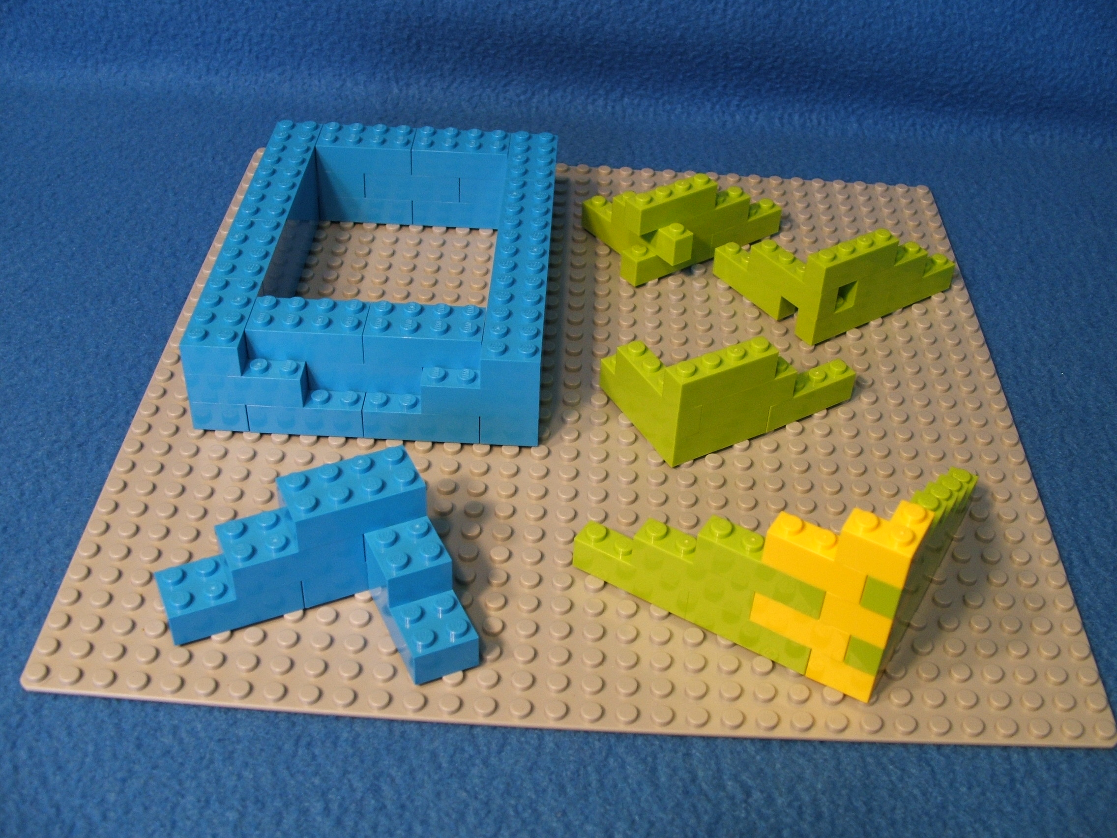
Using elements of different length like this is one way to combat meshing issues AND provide for a solid build. Shown below are some basic examples of this in action.
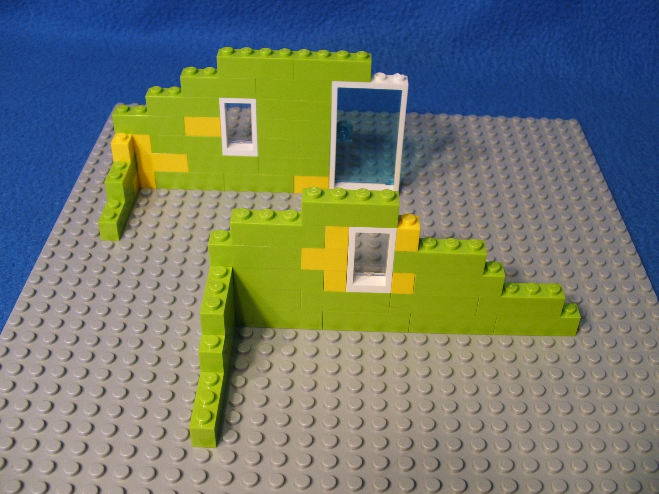
Keep in mind that the key to SOLID structures is done by avoiding adjoining gaps (where elements meet) which can happen when mixing different lengths of bricks or other elements. In the examples above, look at the right side of the window. Notice there are FIVE layers in a row with a gap between two adjoining elements (the window AND the bricks below and above the window). This creates a long run with NO horizontal connection and produces a weakness in structure strength. If that window would be moved just ONE STUD to the left, it would lessen the gap run to just the THREE layers (just the window itself). Note the brick over the door IS a good mesh as it covers TWO of the four STUDs allowing the next brick to use the other two STUDs and keeping the gap between them in the CENTER of the door span. Thinking about meshing REQUIRES also thinking about the gaps.
Top of pageJUST MESHING AROUND:
So now we know that STUDs are 8mm apart and thus form a grid like system where 90° corners are common. What about diagonal, angled, and curved builds? Lego provides some elements to assist with these but otherwise they can be very tricky to mesh. For example:
Let us consider a 15 hole beam being rotated on a baseplate with the first hole anchored in place. Solid meshing occurs at both the 0° and 90° points. But beyond that there are only a few points at any other angle which yield good meshing.
The STUDs are represented by the red circles with green outlines. The path of the holes on the beam as it rotates are represented by the blue lines. Meshing occurs only where the blue line crosses directly in the center of a red STUD.
We can tell from this that there is no useful way to create angles from the connections. Thus most every turn will be a 90° angle from the other element. But there are ways to make things happen, so lets discuss some quickly.
Lego makes many elements in circular shapes. These help to solve the otherwise block style layout. The STUDs and tubes on these elements still conform to the standard grid (with a few exceptions) but at the base there are notches cut from the wall where a STUD would collide with it. This allows the elements to be placed where they ordinarily would not fit. While these elements have a curved edge, block shaped elements placed on top will still follow the grid like concept. Thus if the goal is to continue a curve, you must use other circular elements.
Lego also makes triangle and octagon elements. As above for the circular elements, most of these conform to the standard grid with notches cut where STUDs would collide. Elements do not mesh across the 45° sides of these elements, except for the Lego elements designed for that purpose.
There are exceptions to the above. Lego DOES make an "A" style element, shaped like an uppercase A. This has the two sides at a 45° angle from each other and the STUDs and tubes follow the SIDES (thus do NOT conform to the normal grid). Because only one side meshes with the grid, these would mainly be used to join two separate structure together at a 45° angle.
There are some other ways to go "off grid", which I will touch on in the section about Tips and Tricks later.
Top of pageA NEW PLANE:
A PLANE (geometry not the flying kind) is reference to a flat surface in dimensional space. So a baseplate on a table is a "horizontal plane" as it extends out (in this case, in two directions) horizontally across the table surface. Anything extending upward from that baseplate is on a "vertical plane" from the baseplate (for height measurements). We can express measurements on these planes using an axis oriented coordinate system using symbols to represent each axis. I will use "X" to represent distance from left to right, "Y" for vertical rise distance (upward), and "Z" for depth (front to back moving away).
To simplify things, I will mostly refer to STUD counts and BRICK HEIGHT for these distance measurements but they can also be expressed in millimeters or other ways. So in terms of the baseplate on the table, it is 32 (STUDs) of distance in both the X AND Z axis on the horizontal plane. We will ignore the height (Y) of the baseplate because we are using that just for the purpose of STUD connections to anchor some examples to and not as a part of the model itself.
A "LAYER" will be each collection of elements ABOVE the baseplate as we build upward. Layers are measured by X and Z on the horizontal plane just like the baseplate, but can also be referenced by the height distance of Y ABOVE the baseplate.
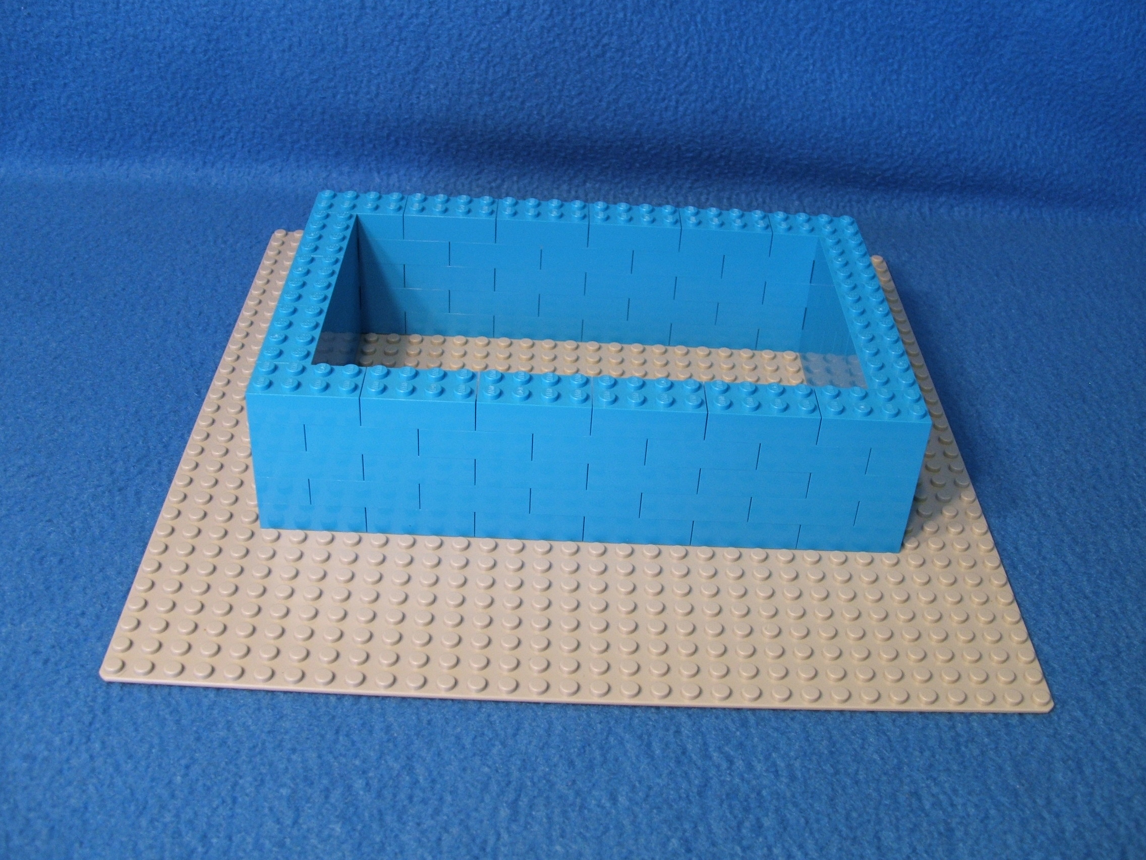
Shown above we have a rectangle on a baseplate. It is measured as 24 (STUD) X, 16 (STUD) Z, and 5 (brick height) layers Y. Each layer is made up of 18 2x4 bricks on the horizontal plane above the baseplate. These are the basic planes for building Lego models.
There are elements which add new planes to the basic two planes. "Angles", "hinges", and "swivels" can be used to take builds in new directions. Here we will discuss angle elements.
An angle is any element which has knobs on the sides. A knob works like a STUD except they are mounted on the side of the element and change the direction of the build by 90°. If that were the only change, this would be a very short segment of discussion. But as shown below, that is NOT the case. Some elements also have knobs with a smaller hole in the center, which allows certain elements to connect to it.
While the connection to a knob is firm, gravity plays a bigger role in disrupting the grip because connecting elements are NOT supported by the top of the element also (like STUD connections have). Since the only thing holding the connecting structure on is the knob itself, there is a limit to the amount of weight that this connection can withstand. Therefore, these work great for small add ons but larger additions should use more bracing or just use Technic elements instead. Be aware that the weight of any structure connected to the knob will ALSO have an impact on the connection below the angle element itself as there is extra weight on one side.
There are MANY ways an angle element can be used. They are commonly used for mounting: vehicle bumper assemblies to the vehicle, signs to a post or structure, pictures or TVs to a wall, or attaching tiles or decorations on the side of something. If using it as a simple mounting tool, the biggest thing to consider is the orientation of knobs from the mounting point. If the attached assembly is heavy enough to require bracing OR if it will be attached to the structure at another point also, the relationship of multiple angle elements MUST ALSO be considered.
Because the angle elements change the path of the build by 90°, we then refer to the attached structure on its own independant plane system. In fact, usually these structures are built first and THEN attached to the angle element.
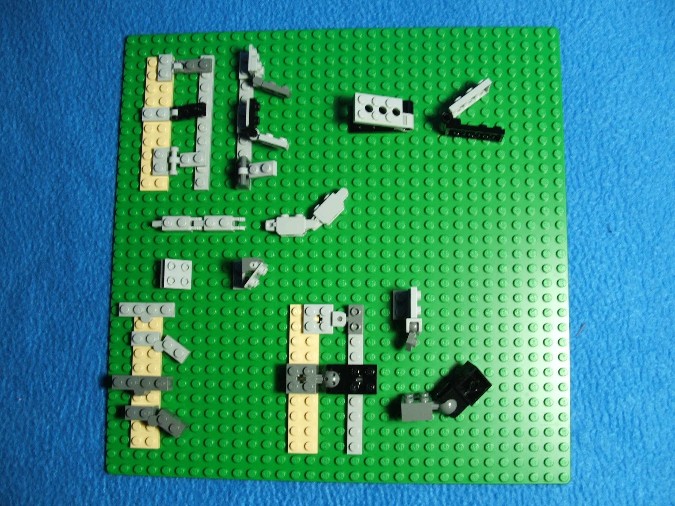
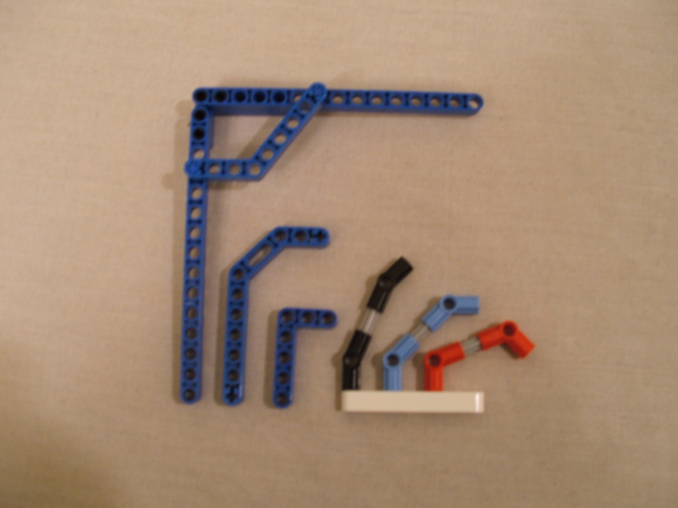
As shown above, there are several types of angle elements with some slight differences in design and positioning. Here is only a few of what is actually available. This is a view of the elements alone (bottom left) as well as how knobs are postitioned in relation to the elements around them (bottom right). From this view alone it is easy to understand there are challenges with meshing as the knob heights are different depending on the style. I will say it again as I had earlier, knowing HOW they work gives a better ability to create with flexibility.
There are several differences to look at here but also some similar traits. Since the four elements featured above are different colors, I will refer to the color instead of the description each time.
- White has a 2x2 knob pattern mounted LOWER than the connection plate.
- Green has a 2x1 knob pattern mounted HIGHER than the connection plate.
- Gray has a 2x2 knob pattern mounted HIGHER than the connection plate.
- Black is a brick with a 2x1 knob pattern mounted directly on its side.
Notice the elements in the lower left which are mounted on the baseplate (Green, Gray, and Black). Because of the extension of the side plate and knobs, these barely fit before striking a STUD and there is certainly no room for mounting another element without interference with the baseplate STUDs. For this reason, the examples in this picture are placed ABOVE the baseplate and they are mounted at the edge of these bricks. Commonly angle elements will be mounted this way in all models, leaving enough room in ALL directions for the element knobs AND any attached structure so as to not contact nearby STUDs or other elements.
All of the elements EXCEPT for Black are PLATES which have the knobs on a HALF PLATE (thinner than a plate) which extends out ("OFFSET") from the normal face of an element. If you want the mounting assembly to be flush with the surrounding elements, then you must use elements whose knobs are directly on the side (such as the Black).
For simple mounts all that needs to be considered is whether the mount is to be above or below the base of the angle element. White is used for below while any of the others can be used for above.
Each mount plate is 8mm per knob. So the 2x2 mount would be 16mmx16mm and the 2x1 would be 16mmx8mm. Does the 8mm value sound familiar? There IS a reason I took you through the sea of math before! 8mm is the SAME as the distance between the centers of adjoining STUDs AND tubes of elements. Thus, knobs can allow elements to connect just like STUDs do. Knobs are also centered on their element (like STUDs) so the center of the knob is 4mm from the edge.
Notice that knobs on the downward mounted elements line up with each other, knobs on upward mounted elements line up with each other, but the downwards and upwards knobs do NOT line up. Also, Blacks knobs do not line up with the other upward mount elements knobs. This is due to the orientation of the mount plate from the angle elements base. On the upward elements, the mount plate starts at the base of the angle element going up. On downward elements, the mount plate starts at the TOP of the angle element, whose height is 3.2mm (1 plate height). This puts it 3.2mm higher than it needs to be to line up with the upward mounted knobs. The center of the knob on the black angle element is 5.6mm above the base and 4mm below the top. So compared with the Gray or Green (bottom knobs are 4mm above base), Black knobs are 1.6mm higher.
The information above is VITAL if there is a need to use more than one angle element to side mount an assembly. There has to be a way to get the knobs on multiple angle elements to be spaced in a multiple of 8mm apart from each other. Thankfully the math works out yet again!
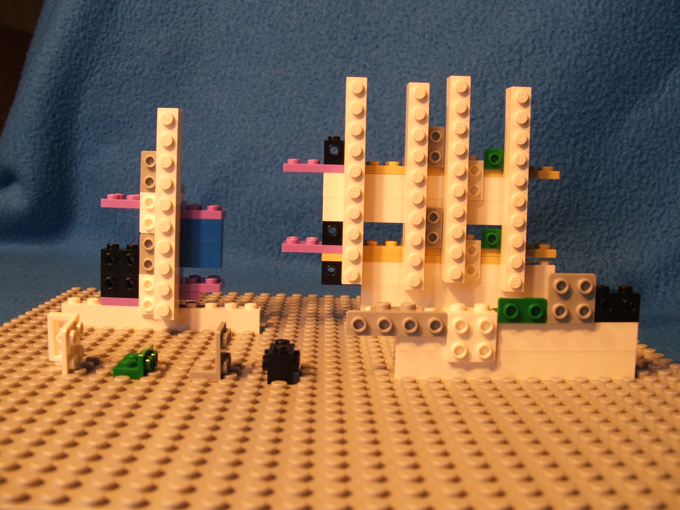
Consider the strange looking structure at the upper left of the picture above. On the left are two Blacks stacked, on top of a (purple) plate. Just right of that are two White and two Gray stacked in an alternating manner. On the right side of those is a 1x10 beam mounted vertically. The support elements behind are placed so they can be seen. The base beam is for support only and will be ignored for our measurements.
The lowest angle element (White) is three plate heights up from the base. The angle mount plate is one plate height, so the top of the angle mount is FOUR plate heights (4 × 3.2mm = 12.8mm). We just learned knobs are 4mm from the edges, so the center of the top row of knobs is 8.8mm above the base. Above we learned the center of the knobs of Black is 5.6mm above its base and we add 3.2mm for the plate it is on for a total of 8.8mm above the base beam. So now the knobs line up! Since the knobs of the higher Black are 9.6mm (one brick height) up, it does NOT line up with the next row (bottom knobs of lower Gray) which are 8mm higher than the row below.
The Gray is stacked directly on top of the White below it. With this placement, the knobs ARE the required 8mm apart to allow alignment as the downward angle starts at the top of the element and the upward starts at its bottom. Between the bottom of the lower Gray to the top of the upper White is 32mm (4 knobs × 8mm each). That is 10 plate heights (3.2mm each) but we need to deduct the two plate heights which are part of the angle elements. So in order to get the required meshing, we simply place 8 plate heights (25.6mm) of material between the two angle elements. Here this is accomplished with two blue bricks (19.2mm total) and two purple plates (6.4mm total) for 25.6mm (19.2 + 6.4) total height. Then, just as below, the top Gray can just sit on the White below it.
Now, because ALL of the knobs are an even 8mm apart, we can mount a beam vertically using all four center angle elements! Using simple Lego math and the right elements, we can mesh angle knob placement even over a large area.
So now the even stranger structure (upper right in above picture) might make a little more sense. One thing it shows is that the vertical beams are NOT all the same height off the base. Only the beams connected to the Gray and Green match (and we learned a bit ago why this is). But all of the beams MESH with the angle element knobs as each set of angles is 32mm of height difference (three brick and one plate height) which equals four STUD length (8mm × 4 = 32mm).
Notice also the three
Black angles at the left.
The center of the knobs
on the lower two are
separated by two plates
(6.4mm) and one brick
(top part of bottom Black
and bottom part of top
Black) (9.6mm) to make
16mm. This equals two STUD
lengths for a good mesh.
The center of the knobs
on the upper two are
separated by three bricks
(28.8mm) (which includes
Black parts) and one
plate (3.2mm) to make
32mm. This equals four
STUD lengths for a good
mesh. In fact, we can
mesh at every other STUD
by simply adding 5 plate
heights for each
additional two STUD
lengths.
| This table shows the vertical rise in STUDs and the EQUAL vertical rise in PLATE HEIGHT and BRICK/PLATE combinations. | ||
|---|---|---|
|
VERTICAL
STUDS |
PLATE
HEIGHT |
BRICK
SHORTCUT |
| 2 | 5 | 1 brick + 2 plates |
| 4 | 10 | 3 bricks + 1 plate |
| 6 | 15 | 5 bricks |
| 8 | 20 | 6 bricks + 2 plates |
| 10 | 25 | 8 bricks + 1 plate |
| 12 | 30 | 10 bricks |
| 14 | 35 | 11 bricks + 2 plates |
| 16 | 40 | 13 bricks + 1 plate |
| repeat indefinitely .... | ||
BENDING THE RULES:
There are "rules" (so to speak) of bends and tilts. Knowing the rules can help make model design a LOT easier. This section covers some of the basics using "action" elements, mainly hinges and swivels.
Hinge elements allow the attached structures to be moved in a range of angles along a single path. Some allow for a free movement while others move in steps.
Swivel elements allow the attached structure to be moved in a range of angles and ALSO tilted in a range of angles. This means the movement allowed is across the X, Y, AND Z axis from 0° to about 90° each way from the center point. This is usually done with a ball/cup combination although other methods are possible. There are two types: free or friction. Free allows unrestricted movement while friction is easy to position but will remain in that position until enough force causes it to move.
Normally action elements are used to build simple structures which just extend from the main model. Examples include: lights, decorations, and arms or legs for people and animals. These are individual objects which only connect to the main structure at ONE point (the action element). It IS possible to connect the structure to the main model at more than one point, which is called a rejoin structure.
Most action elements are actually TWO elements (often male/female pair) connected together to form a joint. Because of this, it is possible to use different combinations to suit certain needs. As long as the parts are compatible, you can mix and match them.
Shown above are just a few action elements. These are shown with top and side view of each to show the STUD meshing as well as the movement ability. While there are MANY styles, most share some common traits which we will discuss first.
Notice that for each of the action elements shown, the spacing of the joint allows the STUDs on each side of the joint to mesh well with the STUDs of the baseplate. The joint itself is one or two STUDs long, which makes the elements on the other side of the joint mesh with the baseplate STUDs. Note that in some cases the joint itself is larger than the attached plates, which may collide with STUDs. This is why these are mounted on plates above the baseplate. The exceptions to a good mesh are the first and third hinges (upper left group) which have different widths on different sides of the joint (TWO STUDs left, ONE STUD right). An adapter (one STUD in between two STUDs) element may be used to get a good mesh for these.
For action elements which move in steps ("click" type of joint), there is a 22.5° angle difference between steps of locking positions. Elements without steps can be moved to any angle within their range.
With the many options of action elements, choices can be made based upon the model requirements. Things to consider are: type of joint, location of pivot, size of connection points, desired angle and/or tilt, and range of movements.
Even though there are many options, the basics are similar for how they work.
For stand alone structures, the biggest concern is to insure there is enough room for the structure to move around without colliding with other structures. Not all structures attached to an action element require movement (the element can be used just to position something at an angle), but if movement is an option there should be enough room to allow it.
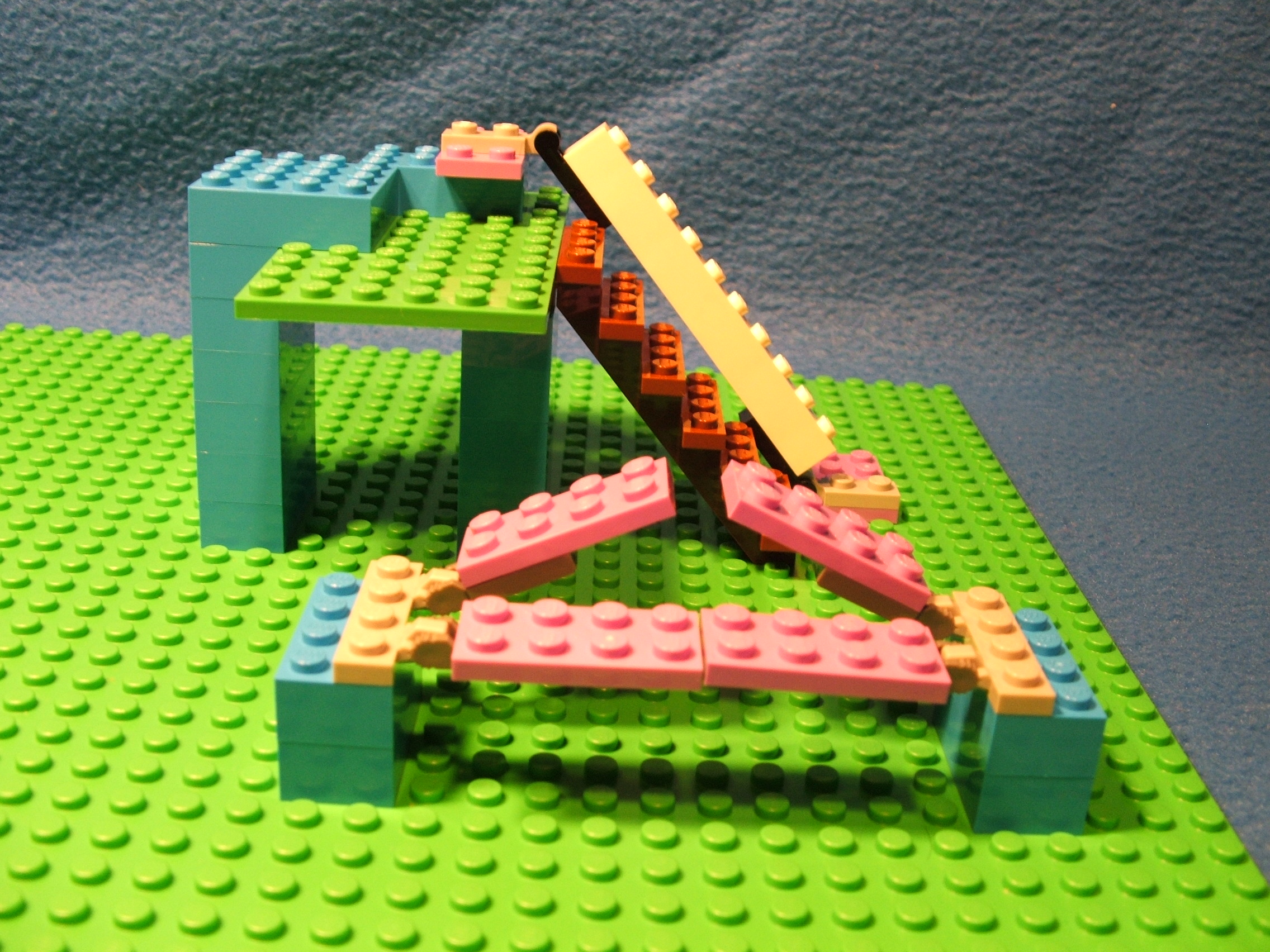
Above are two examples of uses for action elements, A stand alone drawbridge (because there is no connection between the two plates of the bridge) and a rejoin handrail.
The drawbridge (shown both down and raised 22.5°) is an easy build due to the fact of the hinge joint being one STUD long. In the lower postion the plates meet with the usual gap. Thus there is free movement without contact. There COULD BE a connection between these plates, but doing so would halt the ability to move up or down.
The handrail is a rejoin structure as it is anchored to the base AND top. Notice that the PIVOT point is the CENTER of the joint, which is about 4mm from each end of the joint (4mm equals half of the 8mm joint). We discovered in the section of angle elements above that meshing can sometimes be a challenge. When angles other than 90° are involved it is even more of a challenge! Heres why.
First I attempted to get the angle of the staircase. It seems to be just over 50° (about 50.194429°), which is the same rise as a standard 1x1 brick. This makes sense as it is an even multiple (rises six brick heights over a six STUD run).
To make the handrail even with the stairs, I decided to make it ONE brick higher than the stairs. So I had to place the hinge one brick above the top step AND place the bottom hinge (joint) one STUD farther away from the staircase. Since the bottom hinge must be off the baseplate (or the joint will collide with a baseplate STUD), I used a plate there and thus ALSO had to use a plate under the top hinge to make the even seven brick height.
Then I used Lego math to
figure out if this setup
would mesh. With a RISE
of seven bricks on the Y
axis we get 67.2mm (7
× 9.6mm). With a
RUN of seven STUDs on the
Z axis (between the joint
PIVOTs) we get 56mm (7
× 8mm). Since this
forms a right triangle
shape, I calculated the
distance of the slope
(handrail) using the
formula:
SLOPE² equals
RISE² +
RUN².
Which comes out as:
(SLOPE²) =
(67.2²) +
(56²)
(SLOPE²) =
(4515.84) + (3136)
(SLOPE²) =
(7651.84)
SLOPE = 87.47479637
87.47479637 ÷ 8mm
(distance of a STUD/gap)
= 10.93434955 STUDs
This is very close to 11
STUDs. It is NOT exact,
but Lego action elements
allow us a tiny bit of
play. Because the hinge
joints (pivot to edge)
count as 4mm each in this
triangle shape, we
subtract that to get
about TEN STUDs needed
to span this slope. Notice
that it really works too!
I used a ten STUD brick
but any combination of
elements adding up to ten
STUDs would also work.
The same process can be used to calculate meshing with action elements in almost any situation. If you know any TWO of the values (RISE, RUN, or SLOPE) the other can be calculated. As long as it comes out VERY CLOSE, it will normally work. Otherwise try adjusting with plates or different STUD locations to get a good mesh. Keep in mind that it may be difficult or even impossible to get a good mesh in some situations using action elements to rejoin.
Here are the formulas which can be used for calculation:
- RATIO = RISE ÷ RUN
- INCLINE % = RATIO × 100
- ANGLE ° = arctan(RATIO)
- SLOPE DISTANCE = √((RISE²) + (RUN²))
Example:
-
Sample setup:
RUN of 16 STUDs
RISE of 5 bricks
SLOPE is unknown -
Convert to MM:
RUN = 128mm (16 × 8mm)
RISE = 48mm (5 × 9.6mm) -
Find ratio:
RATIO = .375 (48 ÷ 128)
INCLINE RATE = 37.5% (.375 × 100)
ANGLE = 20.55° (arctan(.375)) -
Find slope distance:
SLOPE DISTANCE = √((48²) + (128²))
SLOPE DISTANCE = √(2304 + 16384)
SLOPE DISTANCE = √(18688)
SLOPE DISTANCE = 136.7
SLOPE DISTANCE = 17.09 STUDs (136.7 ÷ 8mm)
Not everything attempted will work out. Sometimes compromise of the builder and the elements can be reached. However with the knowledge of HOW elements function and a little bit of math here and there, there is a good chance a model can be build at least close to the original plan.
Measured in degrees
Just for extra information, the SLOPE of plate and brick is shown above. I did not find much on this during my research so I decided to include it here as I have found it can be useful.
Above we can tell that a 1x1 brick is 50.19° slope from bottom left to top right of the brick. This is over 45° which makes sense as a brick is taller than its width or depth. A 45° slope can be obtained with a distance of TWO STUDs and FIVE plate heights (or one brick and two plates). These figures can be used to build structures which rise at certain angles, such as stairs, hills, slides, or even train track inclines.
These slopes are of the brick itself. Lego makes sloped brick (has a flat surface on one side which is at an angle to the other sides of the brick) which have different angles than those stated above. This is because the slope does not start at the base, there is a small flat surface below the front of the slope for structural support. So while I am on the topic, I will quickly discuss these.
From a meshing view point, the size of the element may be of more importance than the slope angle. The sloped surface does NOT have STUDs so nothing will attach to it which we need to calculate. Since the connections are to the STUDs, the location of the STUD is normally what will matter for calculation.
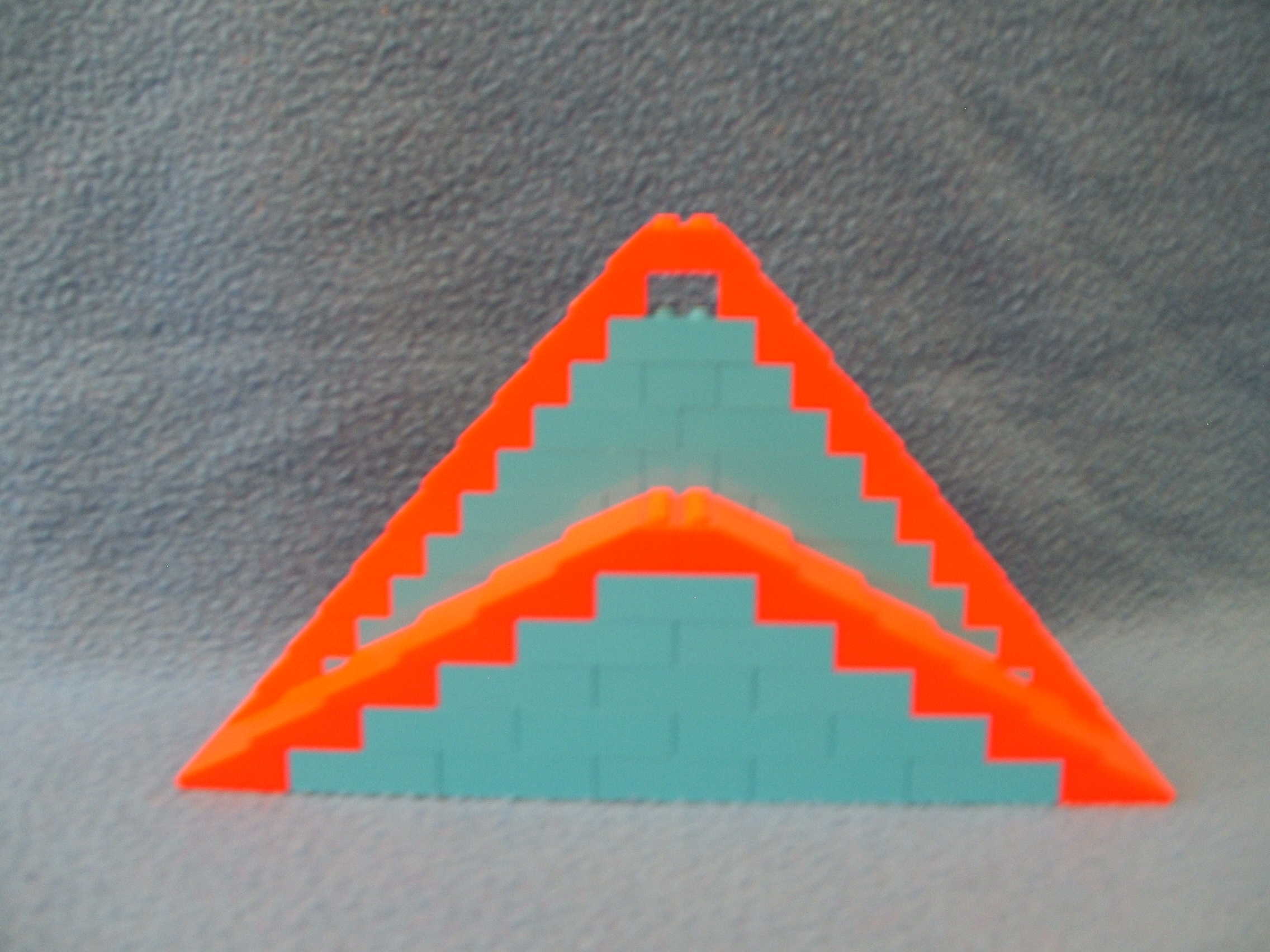
On the other hand, the slope angle determines the rate of incline and CAN be important. For example, a roof built out of sloped elements might reach a peak at the center. So half the distance is going up and the other half is going down. Any sloped elements can be used, but if the HEIGHT of the roof matters, the right incline ANGLE should be used. The higher the angle, the higher the roof.
The shorter roof uses 3x4x1 slope elements which have a stated 25° slope which spans a TWO STUDs run and a ONE brick rise. The ACTUAL angle of the roof is 30.96° (the slope of a 2x1x1) because the slope does not reach the bottom of the element. Note this structure is six brick heights tall.
The taller roof uses 2x4x1 slope elements which have a stated 45° slope which spans a ONE STUD run and a ONE brick rise. Again, the ACTUAL angle of the roof is about 50.19° (the slope of a 1x1x1). Note this structure is twelve brick heights tall.
Notice that the short roof is HALF the height of the tall roof. If you think about it this makes sense as each slope element spans TWO STUDs instead of one. So twice the run equals half of the rise.
If you try to use the formulas (from earlier) to calculate the rise or run from the STATED angle of the sloped portion of the brick, the result will be inaccurate. Using the ACTUAL angle instead yields a correct result. THIS is why I have included those actual angles in this document!
And just for information, the height of the small flat surface below the slope is 1.6mm (the difference between the 8mm STUD/gap distance and the 9.6mm height of the brick) on these elements. Some slope elements may have a different value, especially those which have heights not equal to even brick height multiples.
Calculating many other elements can be done in the same manner. This includes, inverted slope, arches, bevel or curved tiles, and even domes or parabolics. Using the actual angle of the element is not only more reliable, but it is often done more easily than calculating complex shapes used in some Lego elements.
Top of pageTIPS AND TRICKS:
Lets pretend for a moment that you are not a Master Builder and that you do not have instant access to EVERY element which Lego has ever built. For most of us, that is NOT pretending. So there may be times where a little creativity is needed even if a similar Lego element could be obtained or eventually produced. Below are just a few tips or tricks, all are LEGAL as connections go.

-
1x1 as a hinge:
Using a 1x1 element as a swivel is an easy way to mimick a hinge, especially in tight spaces. Either a plate or brick can be used for the same effect with different heights.
Shown above is a spiral staircase which makes use of 1x1 round plates to lift each step enough to allow it to rotate without colliding with the STUDs of the step below it. Here, another 1x1 is mounted on the underside of each step to limit the swing over the step below.
A curved wall can also be built using 1x1 elements to connect the ends of other elements between layers, usually in a staggered pattern (as shown above).
The most important thing to remember when using 1x1s this way is that this connection is not very sturdy unless there is some means of bracing. The larger the structure the more bracing is required. With the staircase example, I support it in the middle so it just hangs for this picture. If it were only anchored at the bottom it would tip over. If only anchored at the bottom and top, it could collapse in the middle if any weight is applied.
-
Hinge swapping:
There are many types of hinges available but a lot use similar types of joint connections. This allows a builder to mix and match what they have for another purpose or size.
There is a large variety of clip/rod combinations which offer different properties when mixed.
-
Upside down:
If the need should ever arise for a portion of a model to be upside down, this can be done with two angle elements (as shown above).
Keep in mind about the weight limitations and bracing needs which I have discussed earlier. Also notice that the upside down portion is NOT an even mesh with the original structure due to the plates and location of knobs of the angle elements.
So far I have found only ONE reason to build something upside down and later found it could be done better with an upright element I was not previously aware of. But still the fact that it CAN be done is interesting to me.
-
Swivel to position:
There are several types of swivel and turntable elements available. While these are great for making things go around (like a carousel), they can also be used to tilt something at any angle of the 360° range.
I used this once where a small swivel was mounted to an angle element (as shown above) and I had a vehicle attached to the swivel. This was mounted on a blue wall with ramps at each end. The vehicle was tilted (with the swivel) to simulate it had just left the ramp and was flying through the air. I though it was a pretty good effect.
FIGURE IT OUT:
So far everything has been about meshing of elements. But there is another very important thing to consider for models, the MINIFIG. A minifig (mini-figure) is any of the variety of Lego people or animals.
If the model will include a minifigure, the size of the model should be of a close scale to the figure. For example, a vehicle should be made so a driver would be able to see out the windshield and reach the steering wheel. If realism counts, the size of the minifig is crucial to the design! Also consider the room needed for human fingers to get to the minifig for access to it.
Here I will only discuss the regular minifigs, but the dimensions of others (such as Duplo) can be easily obtained using a ruler which includes metric values. The goal for the purpose of this document is an approximate measurement relating to plate height (3.2mm increments) so that can be considered in model design.
The three types of minifigs I will discuss are adults, children, and Friends. Generally they are very similar but have differences which should be noted. This covers the minifig itself and extra space should be allowed for different hats, hair styles, and any other accessories.
Front to back, the minifigs are about one STUD deep (8mm) with the arms down along their sides and the arms can extend over one STUD forward or backward. Across the front, they are about two STUDs wide (16mm) at the feet and four STUDs wide (32mm) at the shoulder and arms. The arms can travel above the head and below the bend of the waist but do NOT go below the bottom of the figure even in a sitting position.
The children have short legs and do NOT bend at the waist. Adults do bend at the waist and are just a bit taller than the children. Friends are shaped more like a human and are a bit taller then the block shape adults.
Below is a table of dimensions in plate heights (3.2mm each) from the bottom of the minifigs to the points noted in the first column. Note the value for the "Arm Pivot" is where the bottom of the arm would be if the arm is forward such as resting on a table in front of the figure. This serves as a good value for height of counter tops or such. The "Sitting difference" value is the number of plate heights to deduct when a minifig is in a sitting position.
| PLATE HEIGHTS | |||
|
FROM
BASE TO |
CHILD | ADULT | FRIENDS |
|---|---|---|---|
| TOP OF HEAD | 10 | 12 | 14 |
| SHOULDER | 7 | 9 | 10 |
|
ARM PIVOT
BOTTOM |
5 | 6 | 8 |
| WAIST | 3 | 4 | 6 |
|
SITTING
DIFFERENCE |
- | -2 | -5 |
The value for the top of head is also useful in calculating the number of STUDs for a minifig laying down (such as on a bed). With hair or a hat, allow for about five or six total STUDs.
Minifigs can have a range of dimensions based upon arm and leg position as well as abdomen bending. So if a model has a minifig which can be movable, enough space should be given to allow for that.
Top of pageTHE TECHNIC-AL ASPECT:
Lego makes Duplo for very young children, Classic for pre-teen, and Technic for teenagers. The Technic elements are more like a construction set than the Classic brick elements. Instead of walls and doors, Technic sets model vehicles that move or cranes that lift and turn.
For this document, I will focus on the basic Technic building elements. Since most of this will refer to material covered in earlier sections, understanding that is a good idea before reading the sections below.
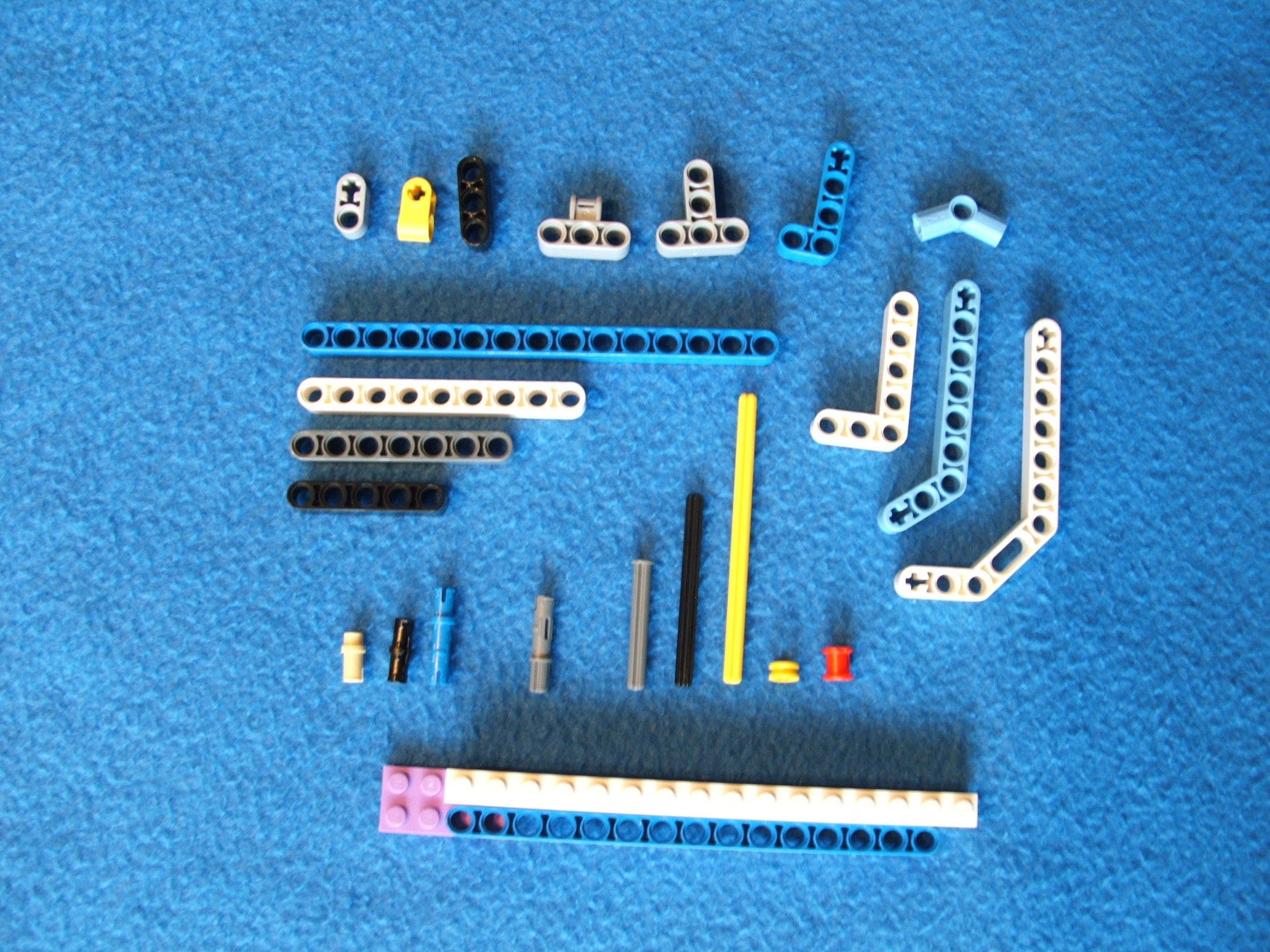
and connectors.
Technic pieces look much different from Lego STUD connect elements in that there are beams with holes and many elements devoted to creating bends, angles, and moveable connections. Even so, Technic uses the same basic concepts as I have covered above. So we will run through some of these rather quickly.
One huge benefit that Technic have over the bricks is that most Technic elements do NOT have a defined bottom or top. Instead, beams use holes for their connections, which can extend from EITHER side (or even BOTH sides) of the element. And beams can be positioned horizontally, vertically, or any which way you want. I need to mention that SOME Technic elements DO have STUDs or tubes so they can connect with the Classic Lego elements.
The foundation of Technic is the BEAM. In some ways the beam is similar to a brick. The holes are spaced 8mm apart, the same as brick STUD spacing. In fact, brick STUDs fit into beam holes, although that type of connection does not provide a legal connection. At the bottom of the picture above, a 15 hole Technic beam is next to a 16 STUD brick to show the similar positioning of STUDs and holes.
So pretty much all of the math previously discussed for bricks ALSO applies in Technic. There is more focus on angles in Technic math, but the concepts from earlier will still apply.
Connections occur at the beam through the holes. "SNAP" connectors lock (snap) into the hole to join elements. There are two types of Snaps, free and friction. The free type allows the beam to easily rotate while the friction type is a little bit bigger and holds the beam more firmly. Cross axles (shaped like a cross "+") can also travel through the holes but rotate easily inside. Some elements have cross axle holes which ONLY accept the cross axle elements. These are designed to grip the cross axle to either keep it from rotating OR to allow it to rotate the beam.
Because the connectors lock into place, the connections are stronger than the STUD/tube type of the Classic elements. So with Technic a solid model does not require as many points of contact. You still want to insure stability, but can often do that with as few as one or two connections per joint. Fewer contact point demands also means that elements do NOT have to be stacked together, so fewer elements can be used to create larger models.
While Classic Lego elements are best for building solid wall structures, Technic elements are best for building models with a framework style. Commonly the core of the model is built first and then any extensions are added on. This is NOT the only way to build.
There are two main challenges when building Technic models: meshing and joining. Meshing issues are the same situations and solutions as earlier discussed.
Joining is the actual joining of elements, specifically the snap connector and element. Connectors fit tight, which individually is not a problem to be inserted into a hole. Sometimes though, a beam will have many connections made at the same time (such as joining two sections of a model together), which may be harder. Combine that with a good mesh situation and solid construct, it is even harder. So it is often helpful to plan ahead by installing connectors in advance of adding the beams.
1x1 brick with hole
2 hole Technic beam
Measurements in MM
Shown above is a brick with a hole (so it is really a Technic element) and a 2 hole Technic beam. The centers of the holes are aligned in this figure to better show the relationship. There are MANY differences to note but also some similar qualities.
For both the beam and brick version, the diameter of a hole is 4.9mm. There is a notched out circle around the hole (used by the snap connectors as an anchor point) which is 6.2mm in diameter, but this measurement is not too important for the purpose of this document. If there is more than 1 hole in an element, their centers are 8mm apart (the same distance as STUD spacing). Connections work the same way for both elements.
The brick is 11.4mm tall (9.6mm for the brick and 1.6mm for the STUD). The bottom 2mm (approximate) is reserved for the tube area (to accept STUDs for elements under it) which is shown above as a blue line on the brick. Placing any portion of the hole in that area would disrupt the ability to stack as a normal brick does. This leaves 7.6mm of area on the brick to have the hole at. And as it turns out it IS centered in that area, 3.8mm of distance between the top of the brick and 3.8mm from the 2mm tube area. So the center of the hole in a brick is 5.8mm from the base and 3.8mm from the top (not counting the STUD).
I need to mention that sometimes the holes in the brick elements are located directly below the STUD (such as shown above) but are often in between the STUDs. For purpose of Lego math calculation just add or subtract the 4mm of horizontal space as needed to adjust for this.
The beam shown above has its holes level with the hole of the brick. Note the extension of the top of the brick and the top of the tube area of the brick (the yellow lines) as they get to the beam. This shows that a beam is a tiny bit smaller than that area (.1mm at each point). Since a beam does NOT have STUDs or tubes, it does not need the extra height required for those. In fact, if a beam is attached to a brick with a hole in the manner shown above, it will be HIGHER than STUDs of elements below it and LOWER than the base of elements above it. So in this fashion, Technic beams "play nice" with brick elements.
A beam is actually 7.4mm high (the side with the holes). There is 1.25mm of material between the edge of the hole and the edge of the beam. The fact of the 7.4mm height means there is a .3mm gap between adjoining elements due to the 8mm spacing (similar to the .2mm brick gap). Note that the ends are ROUND (unlike the block shaped bricks) which means that this gap remains even at rotated angles.
If there were such a thing as a 1 hole beam, it would be 7.4mm round. Thus we can calculate the length of a beam by adding 8mm for each additional hole. A 2 hole beam is 15.4mm. A three hole beam is 23.4mm and a 15 hole beam would be 119.4mm. Super easy Lego math!
Cross axle holes have the same locations as circular holes. They are 4.8mm in size to match the size of an cross axle element. But since they are spaced 8mm just as a regular hole, the math is done the same way.
There are also bricks with snap connectors mounted on the side. Again, these have the same location on the brick.
As for the beams and connectors which bend, there are only a few angles. Using the right combinations (and some trigonometry), a wide assortment of shapes can be constructed. Several angles are multiples of 22.5° such as: 22.5, 45, 67.5, and 90.
A special beam with an angle of about 53.13° is used with a right angle (90°) corner for bracing as shown above.
Building with Technic is done in a variety of ways as with any Lego product. After an idea is formed of what the model will be, elements are placed together to create that. But Technic models usually look like a bunch of parts stuck together rather than a smooth structure like the bricks make. Some creators like the effect while others mix in the Classic Lego elements to provide a smooth shell. I will repeat what I said at the beginning, each person should build at the level of their ability. Also, it is more important if the CREATOR likes the result than others do as each of us has different opinions on everything.
Top of pageGEAR IT UP:
Although this document is far from a complete guide to model builds, I would not feel good about it without a word or two about the mechanical aspect of Technic. Models are just stationary items unless there is some movement involved. Wheels can be slapped on most anything to allow it to roll. But often a model will include some type of moveable structure.
Movement may be invoked either manually or with a motor. Mostly the mechanics are very similar. Adding Lego Power Functions to a model can be done at a reasonable cost in my opinion so it is a good option.
There are SO MANY ways of doing mechanical builds that I will not even attempt to cover that area. However, this document is about MESHING and that is a very important part of mechanical building.
Movement is transferred from one point to another by some type of object. An axle, a gear, a string, or any of other assorted items. The focus here is on gears mounted on axles as this is a common method to use.
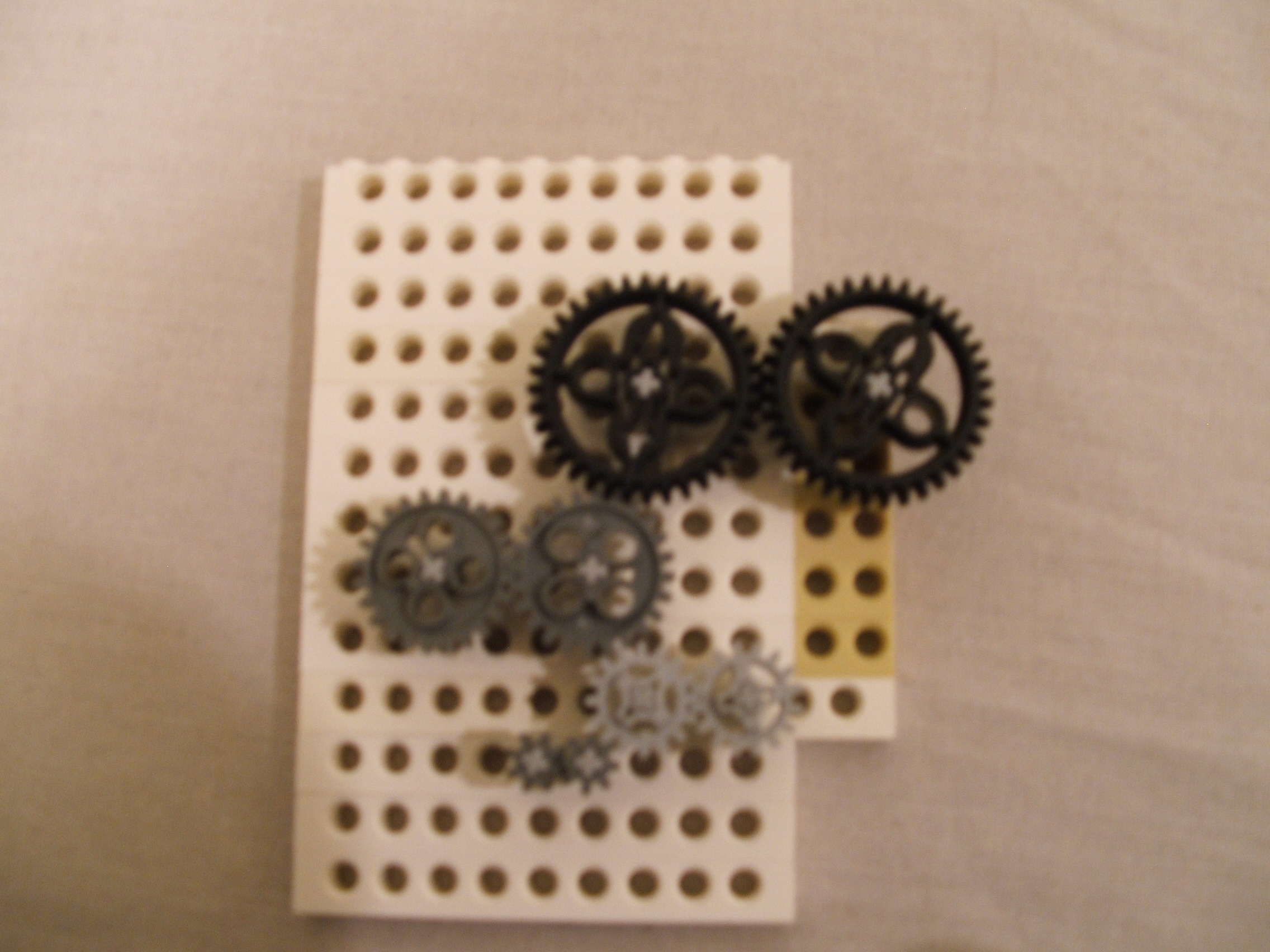
Shown above are many gears arranged so they mesh (mechanically connect solidly). Two of each are shown to show them meshing with each other. One of them connects with a gear of a different size to show how that works too. If ANY of these are turned, they ALL turn. As motion is passed between gears, the gear rotation is reversed. So spinning one gear clockwise will cause the gear it connects to to spin counterclockwise. This whole thing may look like a complicated setup, but there is a simple logic at work.
Earlier we discussed the Lego Unit (LU) and how all elements can be measured with it. Gears are measured by the number of their TEETH and this can be easily associated with the measurements of other Lego elements. The DIAMETER of a gear in MM is the same value as the number of its teeth and the RADIUS is half of that value. Pretty simple.
Above we have gears of teeth counts (top to bottom): 36, 24, 16, and 8. They are ALL mounted on an axle in their center. So lets figure out the meshing to confirm the above picture. We will start with the pair of 8 teeth gears at the bottom and work upward.
8 teeth means the gear has a diameter of 8mm and a radius of 4mm. The radius is the distance between the center (axle) and the gear teeth. If we want to have two 8 teeth gears mesh, we need their axles to be 8mm apart (4mm per gear). This is the same as the spacing between two holes side by side so this works out perfectly! Placing the second gear in the hole ABOVE the first would NOT mesh as the hole distance is 9.6mm (1 brick height).
Next we mesh the 8 teeth
gear with a 16 teeth
gear. The radius are
4mm and 8mm, which adds
up to 12mm. That is 1.5
hole spacings, oh no!
But wait, there IS hope
if we use Lego math from
earlier!
SLOPE² =
RISE² +
RUN².
In the picture above
the gear is mounted
one hole over and one
brick higher. So lets
use those dimensions
to confirm meshing.
(?²) =
(8²) +
(9.6²)
This works out to be
about 12.49mm. Since
there is some tolerance
in gear meshing
(thankfully!), this IS
close enough. We will
find another way to get
a better mesh in just
a bit though.
Meshing the two 16 teeth gears is easy again. Each has a 8mm radius, so combined is 16mm which is 2 holes apart.
A 16 and 24 teeth gear
(8mm and 12mm) are 20mm
apart, or 2.5 holes.
Using values from the
picture above (1 hole
over and 2 bricks up)
we get:
(?²) =
(8²) +
(19.2²)
This works out to be
about 20.8mm.
The two 24 teeth gears have 12mm radius each for 24mm distance, or 3 holes apart.
The 24 and 36 teeth gears (12mm and 18mm) need 30mm distance. Using the 1 hole over and 3 brick up as pictured, we get 29.89mm.
Notice that each time we traveled from the different sized gears that there was some difference in the distance needed and the actual distance. The 8 to 16 transition was .49mm MORE distance and the 16 to 24 transition was .8mm MORE distance. These resulted in the teeth having LESS contact although still having contact. Going from 24 to 36 we had .11mm LESS distance which resulted in MORE teeth contact almost to the point they would jam. So while there IS tolerance, care must be taken to insure enough contact is made for the purpose. The more force which is produced by the mechanism requires a more accurate meshing of the gearing!
So now lets look at meshing the two 36 teeth gears. Each has a radius of 18mm for a distance of 36mm between axles. This distance is 4.5 holes. We can mesh these MUCH easier than we did for the other mismatches.
Notice in the picture above that most of the holes in the bricks are BETWEEN the STUDs. Lego also makes elements (such as the tan bricks at the far right) which have holes UNDER the STUDs, which shift the hole placement by 4mm (half of the 8mm hole spacing). Using this allows us to get EXACTLY the 4.5 hole distance we need for a perfect mesh again!
The goal should always be to get as close as practical. Sometimes the demands of force may limit the tolerance beyond what you have created which will require a design change. There are some ways to fight back though.
So far all of the gears have been mounted independently on axles and turning each other by teeth contact. Another style of meshing gears is to mount them on the SAME axle. This is especially great for different sized gears. If an 8 and 16 teeth gear were mounted on the same axle, the contact point is the axle itself. Thus there is NO NEED to calculate distances for axle placement. The only difference here is that because the axle is the contact point, BOTH gears will turn in the SAME direction now.
Many model builders like to combine their gear assemblies into as compact a space as possible. They do this by mounting two gears on each axle and getting adjacent axles as close together as possible. Such a contraption is called a "gear box" (or gearbox as one word). These can be in any shape, size, or style.
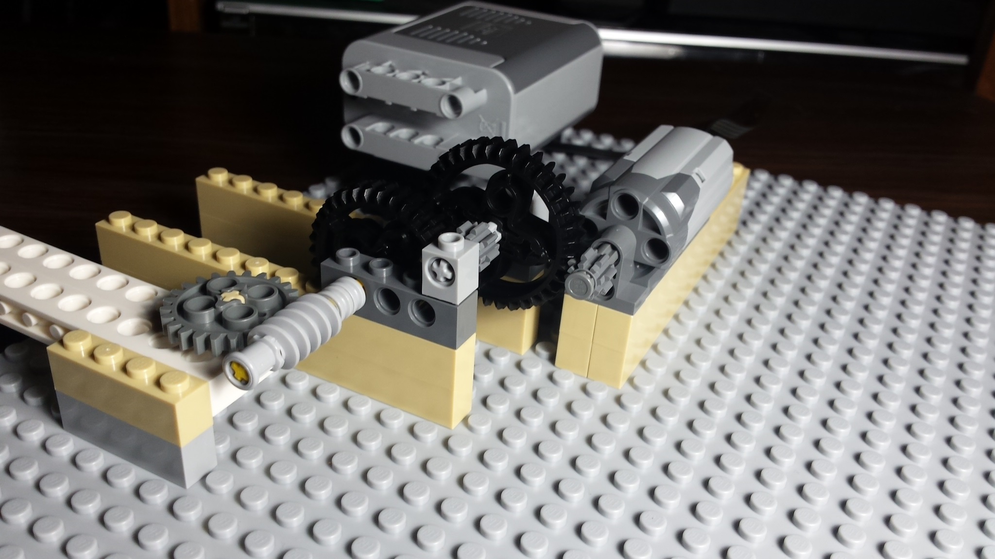
Gears are used to adjust the speed or torque (force power) of a driver (motor or manual) to meet the requirements of the model. Standard Lego motors can operate as fast as 60rps (rotations per second) with minimum load. If using that unadjusted to spin a simple playground Merry Go Round, the minifigs will get very dizzy and probably fly off into the next room.
The speed and torque can be altered by using different gear sizes. Using a small gear to drive a large gear will result in a decreased rotation speed but an increased torque. Using a large gear to drive a small gear results in increased rotation speed but decreased torque ability. Gearing ratio yields an equal impact on both values. Either math or experimenting can produce a desired result for a models requirement. Usually models will require a rotation speed reduction and/or an increased torque when using Lego motors.
Because the Lego gears have the same teeth distance, we can just calculate the gear ratio and gear reduction using the number of teeth on each gear. So if we have an 8 teeth gear driving a 24 teeth gear, that is a "8 to 24" gear ratio and an gear reduction of 3 (24 ÷ 8). For each rotation of the 8 teeth gear the 24 teeth gear will rotate only 1/3 of a turn (as it has 3 times as many teeth). So it would take 3 rotations of the 8 teeth gear to produce 1 rotation of the 24 teeth gear. At the same time the torque ability will increase 3 times also. Having the 24 teeth gear drive the 8 teeth gear would yield a ratio of 24 to 8, a gear reduction of .333-, and a one third decrease in the torque ability.
For this discussion We will use a motor with a speed of 50rps when providing a torque that will spin the Merry Go Round with no minifigs. Thus if we added any minifigs, the motor speed would slow down. Without adjustment (the motor directly drives the Merry Go Round), the Merry Go Round would make a complete rotation 50 times every second! Just a bit too fast!
So lets find out if we can get that Merry Go Round under control. Lets figure a safe speed would be about 1 rotation every 2 seconds, or .5rps. With the motor going 50rps unadjusted, we need a system which can reduce the speed by a ratio of 100 to 1 (for every 100 rotations of the motor, the Merry Go Round will rotate once. Since this is a high ratio to overcome, lets use a high ratio gear combination. We will use 8 and 36 teeth gears for our gearbox. The 8 to 36 gear ratio yields a 4.5 gear reduction.
Attaching an 8 teeth gear to the motor shaft and having that turn a 36 teeth gear on an axle makes that axle turn at the 4.5 reduced rate of 11.11rps (50rps ÷ 4.5). Attaching an 8 teeth gear to that axle and having it turn a 36 teeth gear on another axle makes that axle turn at another 4.5 reduced rate (now a 20.25 gear reduction from the motor, 4.5 × 4.5) of 2.47rps (50rps ÷ 20.25). Attaching an 8 teeth gear to that axle and having it turn a 36 teeth gear on yet another axle makes that axle turn at another 4.5 reduced rate (now a 91.125 gear reduction from the motor, 4.5 × 4.5 × 4.5) of .55rps (50rps ÷ 91.125). That is pretty close to our target of .5rps so lets find out how we did.
The motor rotates at 50rps which is 1 rotation every .02 seconds. With our 91.125 to 1 ratio, we can calculate that 91.125 motor rotations take 1.8225 seconds to occur. So the Merry Go Round rotates once every 1.8225 seconds with this gear setup. And also since the torque ability rose so much, the Merry Go Round speed will NOT be impacted by weight of several minifigs. Pretty close to what the goal was and this way the minifigs will not be that dizzy nor flying off.
Any combination of gears can be used to produce different outcomes. Use the same process as the above to calculate gearbox requirements. Remember though to multiply each axle reduction value from the prior axle rate. In the above example it was 4.5 × 4.5 × 4.5. But use whatever values are appropriate for the gears used.
Top of pageHAPPY MODELING:
I truly hope that some material above gives useful information on building a great Lego model!
I feel that Lego is one of many great toys which encourage creativity, imagination, and motor skills for children AND adults.
Top of pagePage last updated: December 10 2018 11:14:18.
Page visited: 1688
Terrys Place
Book, Motivation speaking, and Bullys
Facebook page
ICIC-ation YouTube channel
Vision and Driver/Bike/Pedestrian safety
Website design
Website programming and utilities:
© 2001-2025 Terry Erickson, All rights reserved.
Website layout and content:
© 2001-2025 Terry Erickson, All rights reserved.
Website hosting:

Proudly made in the USA!