Lego Train layouts
Lego trains layouts are a great addition to displays. They are popular both for the builder and the viewer.
Lego train sets commonly come
with track for a very basic
layout. Additional track can
be purchased to expand the
layout. For this document, I
focus on the track currently
available. These are sets:
7499 Straight and
Flexible
and 7895
Switches and curve
.
It is simple to expand from a basic layout as Lego track pieces connect easily. There are, however, some logistics which have to be considered if you plan to go beyond the basic circle or oval patterns. So first we will quickly cover the track pieces and then go through how they can work together to create a layout.

LEGO TRACK:
There are four different track pieces each having unique characteristics yet sharing some common traits.
- TRACK STANDARDS
-
Each track has a uniform rail
spacing. The
ties
(rail supports) are 8 posts long (edge to edge). Each rail is mounted 1 post in from the tie edge. There are 4 posts between the rails. So the rails are 6 posts apart from each other. Train wheels are guided by the INSIDE edge of the rails.
The ties are 1 plate high. The rails are 2 plates high. So the whole track (bottom of tie to top of rail) is 1 brick height.
Track can be anchored to other Lego elements using the posts on the ties or post acceptors under the ties. However, keep in mind that the posts of curved track will usually NOT line up with baseplate posts. Normally builders let the track sit on the surface (floor or tabletop) as its own structure. Other structures can be anchored to the ties to keep them by the track (such as a station or a crossing).
- STRAIGHT TRACK
-
Each straight track is 16 posts
long and the standard 8 posts
wide.
The style is simple, with 5 ties holding the rails. The 3 ties in the middle are 2 posts long separated by a 2 post gap. The ties on the ends are 1 post long (which when track is connected yields a 2 post tie).
- CURVE TRACK
-
Each curved track is 16 posts
long and 8 posts wide. However,
since the piece is curved it
is not a true 16 post length.
Also, each rail has different
axis
lengths. Since this document does not intend to give you a geometry lesson, lets just say that each curve track yields 1/16th of an entire circle. Doing the math works out to 22.5* of arc bend for each curve track. 4 curves make 90*, 8 makes 180*, and 16 make 360* (full circle). When we speak of angle here we are referring to the ARC angle and NOT the actual angle of slope.
A layout made up of only 16 curved track forming a circle results in an 88 post (about 28 inches) diameter layout (measured from outer edges).
The tie style is the same as straight track except that ties are angled with the rails so the posts do not line up well for securing to other elements.
- FLEXIBLE TRACK
-
The flexible track are short
hinged segments which can be
used as straight or curved
track or any angle in between.
Each segment is 4 posts long,
1/4 the length of a straight
or curved track.
There are only 2 ties here, each 1 post at the ends and only having 2 middle posts.
The arc angle of each flexible track is from 0* to 5.625* (either direction). 4 of these placed at the maximum angle produces the same arc angle (22.5*) as a regular curve track.
Although they are small lengths, the advantage is in the ability to make minor adjustments within a layout. This can be helpful when a layout varies from the common 4-curve corner which produces angles other than a 90* corner or when sidings are used to position track near a structure.
- SWITCHES
- A switch track is designed to allow a train to travel either of two tracks OR merge from one track back onto another. There is a manual control which can be moved to direct the train to the curved part of the switch track. The switch is designed to allow trains to travel from the curved part to the straight part regardless of the position of the switch control.
TRACK EASEMENT:
One VERY IMPORTANT thing to
consider when creating track
layouts is obstacles along
sides of the track path. If
an object is too close to the
track, a train will collide
with it. That is NOT good!
To avoid a train wreck or
property damage, plan ahead
with placement of track and
nearby structures by having
an easement
(empty
space) gap between these.
Along straight track runs, the easement must be more than the overhang of the train car from the rail. Personally I like to DOUBLE that just to be safe (except for a train station where the platform should be close to the train for boarding). So if the train car is 10 posts wide, it extends 2 posts beyond the track (1 post beyond the tie edge). I would insure that any structure is at least 2 posts beyond the edge of the tie.
For curve or flexible track, the easement needs to INCREASE. Just how much depends on several things including the angle of curve, how far the train cars wheels are from the car connectors, and the speed of the train.
Train car wheels are on a swivel to allow them to easily follow the track. The train car itself moves with the wheels, but not in the same manner. When a car goes onto a curve track from a straight track (or curve to straight), the front part of the car passes that point before the wheels do. So the front of the car goes straight until the wheels start making the turn. Thus the front of the car extends further off the track than it would on a straight run. The same applies to the rear of the car. This is true during the entire period of a curve.

The black car is a normal train car with fairly routine easement requirements. The green car behind is a longer body and it has wheels close to the middle of the car, which causes the ends to extend well OUTSIDE of the curve. The last green car is also a longer body but has wheels close to the ends, causing the middle to extend well INSIDE of the curve.
The further the wheels are from the front or back of the car yields more overhang also. This is due to the fact that the edge of the car reaches the bend much earlier than the wheel so it travels more distance in its current direction before the wheel can alter that.
Long train cars can overhang on the inside AND outside part of a curve as well. Depending on the distance of the wheels from the front or back of the car and the length between the wheels, long curve runs can cause a long train car to go beyond a normal easement.
Notice that the two green cars do NOT have wheels or connectors on swivel, which is done intentionally here to show the effects. In the case of the middle car, even WITH a swivel the connector would probably not be able to meet the other cars due to the great offset from the track. Wheels should be located close to the ends of the car to allow for easy joining of adjacent cars.
Fast moving trains can sway out on curves too. In fact a train can tip over if going too fast around a curve, especially if the center of gravity for any train car is high.
Content movement also needs to be considered. Items on train cars can move if they are (or become) unsecure, which is more likely on a curve. If an item moves so that it overhangs the side of the train car, that extends the width of the car thus increasing the easement needed. Another good reason to insure extra track easement.
Another aspect of easement is HEIGHT. If any structure (such as a bridge, wiring, or roof overhang) is above the track, it should be positioned higher than the tallest train car plus the height of the track.
Basic track rules:
It seems having a train just go around a small circle track will get pretty boring after awhile. So lets discuss extending the layout. Planning your layout is much more time consuming then actually connecting the track once you know what you need to build. While it is possible to do a layout without prior plans, you could wind up with two ends that do not meet each other.
Being creative with layouts is
a good thing. Thats what Lego
is all about. But there is ONE
big rule to follow for layouts.
You have probably heard the
phrase, For every action
there is an equal and opposite
reaction
. It is true for
track layouts too!
If you have the 16 curve track
simple circle layout and add
ONE straight track anywhere in
that layout, your track will
separate somewhere else. That
is because of the imbalance
of the layout. The action
of placing the straight track
requires an equal reaction
on the opposite side of the
layout.
The term meshing
is used
to describe the proper joining
of parts, in this case Lego
elements and Lego track. The
original circle layout MESHED
while the additional straight
track caused it to NOT MESH.
In order for the new layout to mesh again, we need to add the equivalent track on the opposite side of the layout. This could be either 1 straight track or 4 flexible track used as straight track. Note that this has to be on the OPPOSITE end, so separated by 8 curve track on each side.
As the size of the layout grows so do the options for meshing opportunities. If TWO straight track had been inserted on the one side, we could use a switch track (equals 2 straight track) on the opposite end also.
With even larger layouts, more
creativity is possible. Using
the flexible track increases
the possible layout shape as it
enables the builder to fine
tune
segments for meshing.
With experience and experiments
meshing challenges can be
overcome. Personally I have
found that by building small
samples it helps to figure out
how whatever you are trying to
create needs to be done. Once
I have it built as I want it,
I document it for future
reference.
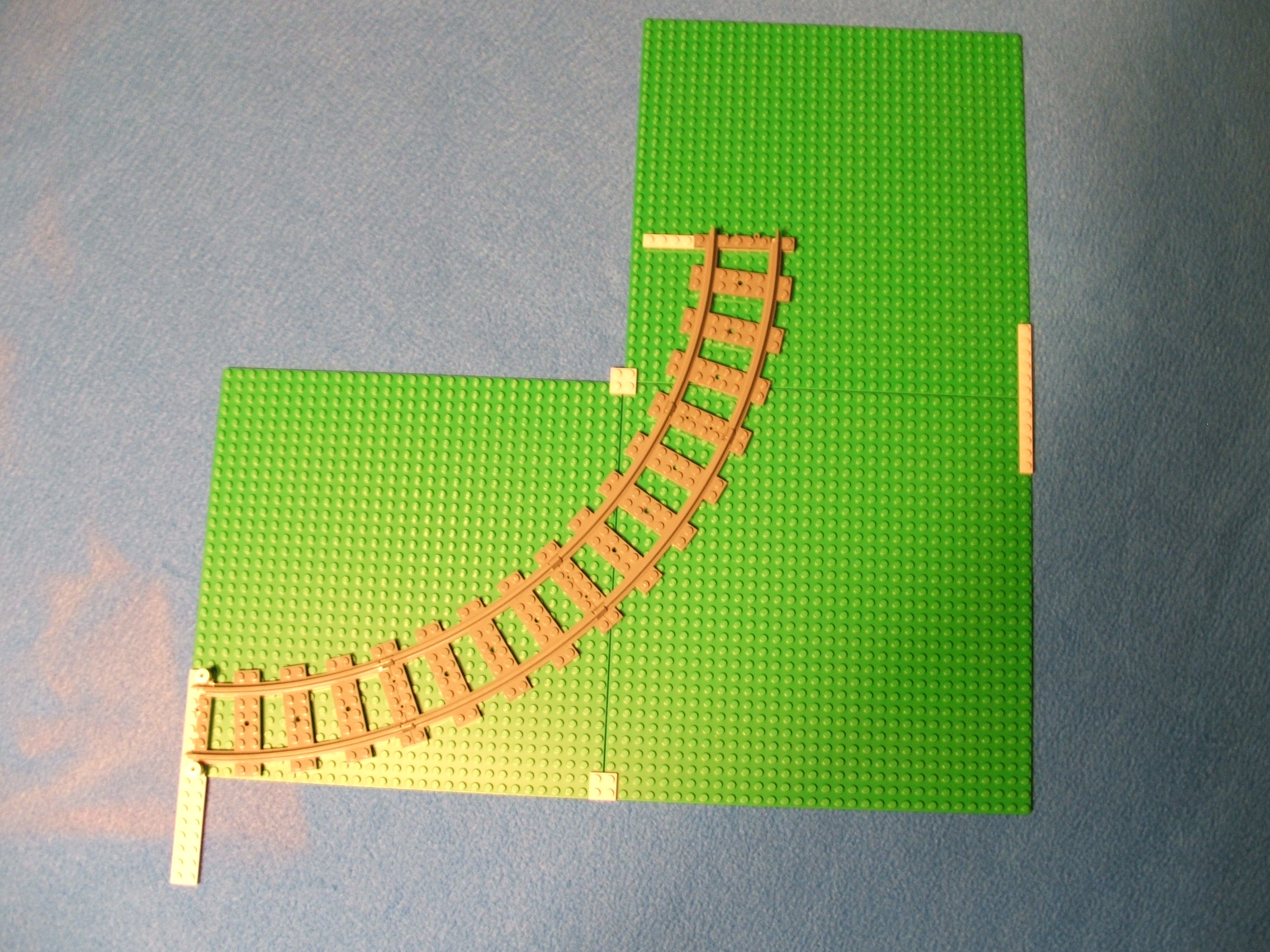
One other aspect of meshing to
consider are track tie posts.
Notice how the curve track sits
on baseplates here. Few of the
posts of the ties mesh with
those of the baseplates. Usually
track is NOT mounted onto a Lego
base. Any structure attached to
track is usually attached to
straight track as the tie posts
DO mesh with other elements.
Beyond the basic:
The switch is difficult to explain in non geometric language. Notice that the two track ends are NOT of equal length. Believe it or not there IS a logic here.
There are a left and right switch element to compliment each other in a layout. They have the same dimensions except the direction of the curve from the main line.
The straight side (I call it
the main line
is the
same length as 2 straight
tracks. Thats easy enough.
The curved side (siding
line
) can be used in two
ways: stand alone or rejoin.
The stand alone type just goes
somewhere (such as a loading
dock or train yard) while the
rejoin type eventually meets
up with the main track system
again. The rejoin style is
more complex in that track has
to meet other track properly.
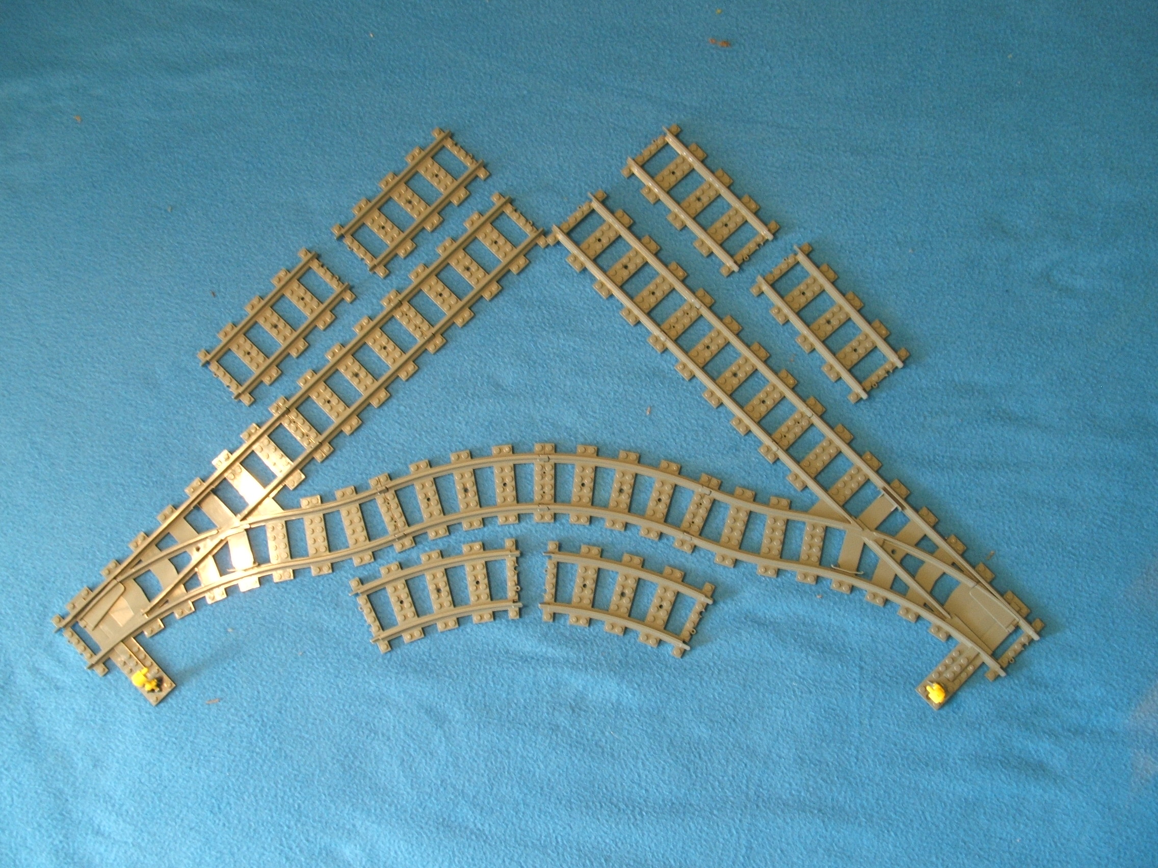
Shown here on baseplate to
show post distances and
above that are the parts
laid out separated.
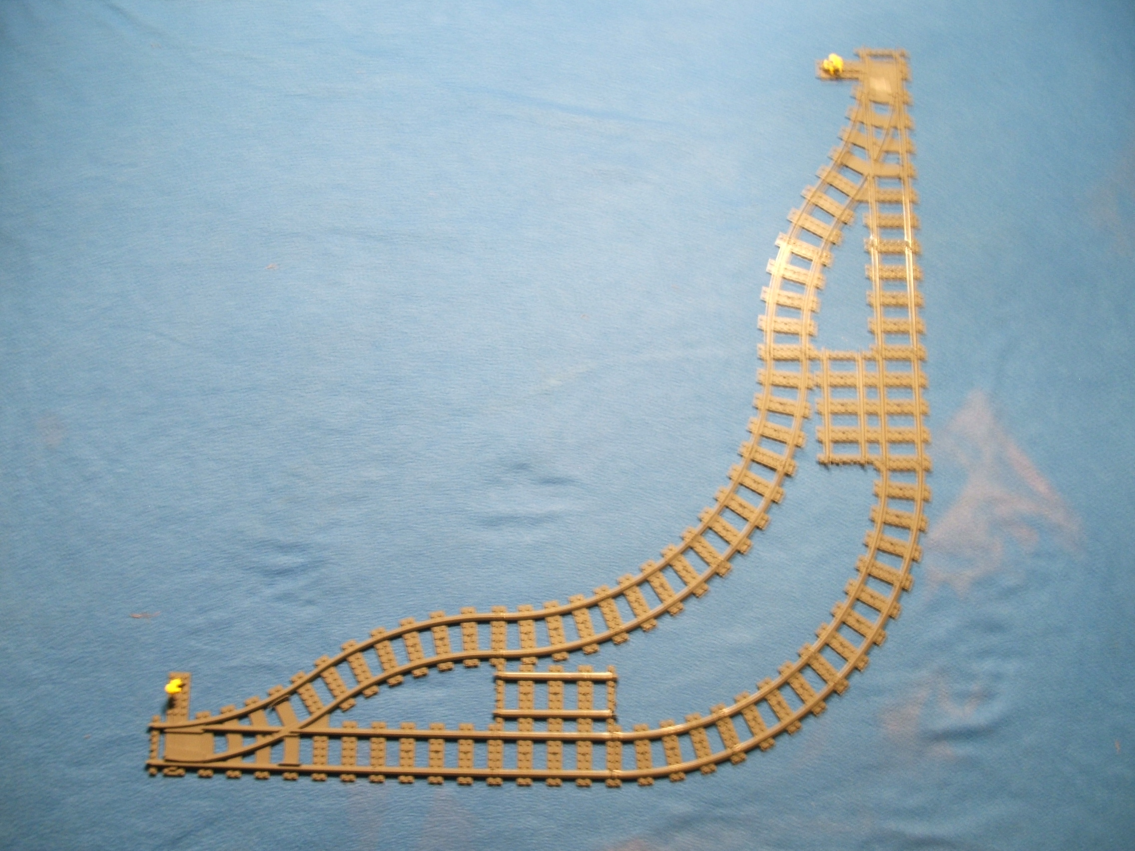
In the most basic layout, the
siding is not that scary. The
angle and length of the siding
line can be combined with one
curve track to make a track
run parallel to the main line.
This siding line would be 16
posts offset from the main
line, 10 posts between tracks.
Using one straight track from
the main yields the same length
as the siding line with the
curve track, each being 48
posts in length. Making this
assembly with both a right and
left switch provides a nice
siding for 1 or 2 train cars.
A longer siding can be made by
adding straight tracks to each
(main and siding) line.
We will look at other styles a little later on this page.
Mixing it up:
Larger layouts offer a great deal of options for unique flare. A layout can go from a simple shape to an unusual route by just mixing up a few track pieces. Just remember that any alterations done must have similar compensation on the opposite end of the layout.
We already know that 4 curve track make a 90* corner. But there is no rule that they have to be together! Placing a straight track between each curve track softens the corner for speedy trains, although it also greatly increases the size of the layout. Even adding one straight track in the middle of the corner helps if layout size is an issue.
As an alternate to the above, 6 flexible track with less bend angle could replace 1 curve track to soften the corner. Use more or less as desired or as space allows.
If you happen to have 2 trains and enough track, make TWO similar layouts. Making one just a bit smaller will allow it to fit inside of the other. One train can run on each layout, in the same OR opposite direction.
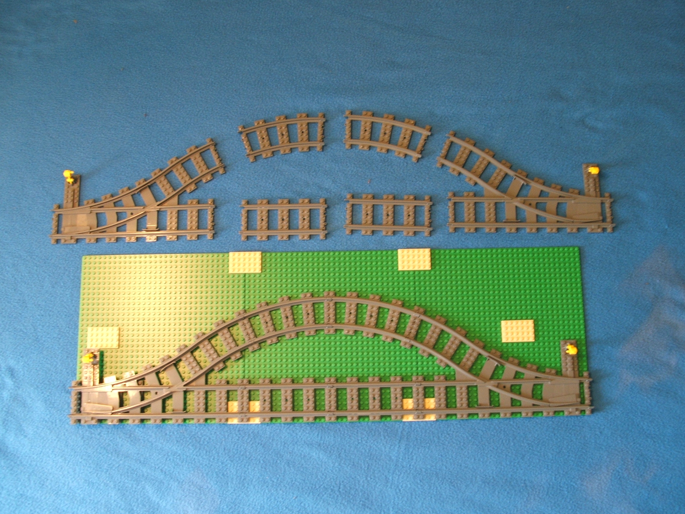
If there is a very long straight run, it can be replaced using a series of curve track staggered to form a wavy line. Note that some flexible track will be required to adjust for the differences in length. This is an interesting effect watching the train navigate the route. Try putting a small rubber or plastic ball on a car with a flat (tiled) bottom and walls and sending the train through the wavy route. Warning: fast trains can easily derail on such a pattern.
Switch creations:
Earlier I described a simple rejoin siding layout using 2 switch tracks. Lets expand on that using switches for a moment. We know from earlier that a switch with a curve track on the siding line equals a straight track on the main line with an offset of 16 posts. Remember this as we move on.
The layout above shows a simple siding spanning a corner. Each switch has a curve and straight track attached as we had earlier to make the ends even. The 90* corner is made of 4 curve track as noted previously. Both the main and siding have the same corner structure. The math for meshing is easy here. Since the OFFSET of the siding is 16 posts from the main, we simply need to increase both of the mains by 16 posts outward (since the siding is on the inside) to compensate for each offset of the switch setup. Since straight track IS 16 posts long, one is added to each branch of the main (as shown above) to mesh properly. If the siding were on the outside, the siding line would get the additional straight track instead.
Using the same method as above, the siding can span TWO corners by adding 1 straight track to each of the outer lines at both ends of the 4 curve corner.
Here we have a layout that does not mesh, but it still serves as a useful calculation example. Previously we determined switch siding track ends with a 22.5* arc angle (1 curve track angle). So adding another gives us 45*. Here I have joined two of these to show proof of that. In this layout, each of the 2 curves make a 45* angle to create a total of 90* angle. What is important here is the fact that the main line tracks of this layout offset each other by 8 posts. Note this is half of the 16 post offset on the simple siding discussion earlier. This is because we did not use a curve track to restore the siding line to be parallel with the main line. Thus we see how even slight differences can throw off everything.
I find it interesting that Lego
does NOT have crossover track
(a +
configuration).
It seems this would allow even
more possible layouts to be
created, even though it would
create a possible collision
point if more than one train
was operating on the layout.
To this point all of the layouts are unidirectional in nature. That means the train will always go in the same direction around the track no matter how the switches are turned. Lets fix that.

With the layout above, 2 left
switches are used to perform a
directional change. A train
traveling counter clockwise can
be made to reverse direction.
If EITHER switch forces the
train to the siding line, the
train returns to the outer loop
in a clockwise direction.
The problem with this layout is that a clockwise traveling train cannot change direction as it cannot be forced to the siding. So the direction change can ONLY occur ONCE and ONLY if a train starts out counter clockwise.
A layout could ALSO have a similar siding made from 2 right switches to perform the same function for clockwise traveling trains.
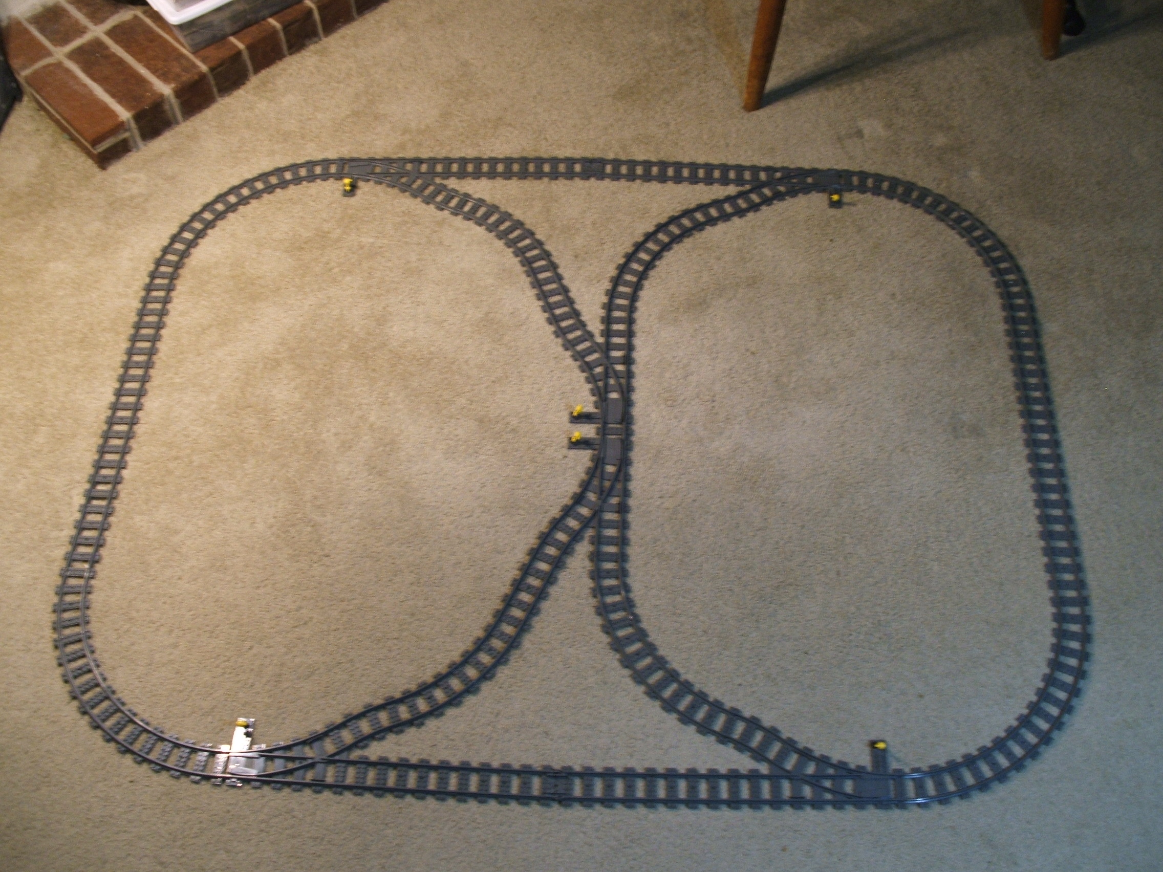
This layout is the most compact
method I could come up with to
perform multiple direction
changes. It measures 68 inches
across by 54 inches wide.
To help explain the action here I will refer to the switches by number, from left to right and top to bottom.
- Upper left (S1)
- Upper right (S2)
- Upper middle (S3)
- Lower middle (S4)
- Lower left (S5)
- Lower right (S6)
Switches S1 and S6 are used to divert clockwise trains to the siding. Switches S2 and S5 are used to divert counter clockwise trains to the siding. If NONE of these are set to divert a train, the train will travel in its current direction around the outer loop.
Switches S3 and S4 are the key to the ability to change the direction of a train. They both serve two distinct functions, to MERGE incoming trains AND to DIRECT outgoing trains.
If EITHER S1 or S2 diverts a train to the siding, S3 MERGES that train to S4. S4 then DIRECTS that train based upon its setting (siding sends the train to S5 for clockwise direction while main sends the train to S6 for counter clockwise direction).
If EITHER S5 or S6 diverts a train to the siding, S4 MERGES that train to S3. S3 then DIRECTS that train based upon its setting (siding sends the train to S1 for counter clockwise direction while main sends the train to S2 for clockwise direction).
So a train traveling around the outer loop has TWO opportunities to enter the direction changing siding and TWO possible direction outcomes upon leaving. Just because a train enters the siding does not mean it will result in a directional change upon leaving.
So depending on how the switches are set, trains can take any of three routes (outer loop, left loop, or right loop) no matter which direction they are traveling in. This provides for a total of SIX different routes in this fairly small layout.
You can even do a figure eight (8) route by constantly toggling S3 or S4. Here is how to do it. Set SI AND S2 to direct to the siding. Start a train at any point on the track in either direction. Now each time the train passes the center, change the setting of S4. Once the figure eight pattern is established it will continue as long as you change S4 after the train passes. The same action will occur if you set S5 AND S6 instead of S1 and S2 and then change S3 after each train pass.
My personal favorite settings for this layout has the train changing directions frequently WITHOUT having to change any switch. Set the switches as follows: S1 and S5 for main, S2, S3, S4, and S6 for siding. Start the train at the top center (between the switches) facing clockwise. While the train can start from anywhere, I just like that reference. The train will travel around using EVERY TRACK SEGMENT before the pattern repeats. During that trip, the train will travel most of the outer loop in both directions. There are of course other combinations of switch settings which will produce a similar effect and other combinations to produce other effects. This just happens to be my favorite. This layout can be expanded in size and then add structures inside and outside of the loops to form a town where the train will pass by EVERY location along the track.
Yet another way to change the direction of a train using this layout is to use the reverse feature of the remote control. For a clockwise direction train, set S5 for siding and S4 for main. Let the train go PAST S5, then back up the train so that it takes the siding and goes PAST S4. Then make the train go forward again. It will travel to the outer loop and go in a counter clockwise direction. Remember though to change S5 before the train gets there if you do not want the train to go onto the siding again. This same action can be done at other switches by using the right combination of settings.
Under and over:
Often tunnels and bridges are
used to enhance a layout beyond
just the track itself. A Lego
purist
is somebody who
uses ONLY Lego elements to
construct things. However, many
other materials can be used to
create simple or complex tunnel
or bridge structures if there
is no requirement against it.
For the purpose of this document,
a tunnel
is created by
ANYTHING that goes over the
track and a bridge
is ANY
period where the track is not on
the same surface as the rest of
the layout. The principals are
similar regardless of the length
or type of the events.
For a tunnel, the biggest concern is for proper easement (discussed earlier). Make sure it is high and wide enough for ALL train activity on the track. Insure that over track wiring is tight enough so it will not move downward.
If the structure over the track needs to hold weight, insure it is strong enough to do so without bending downward. An arch design is a good type of support for holding weight but be sure that the arch offers enough room for the width of the trains at the highest point of the train.
A bridge will have the same concerns as a tunnel in that it needs to be wide enough and strong enough for the purpose. And if the bridge has a cover it needs to be high enough too.
How a bridge is built depends on how long it has to be and how many opportunities there will be for support to some surface underneath. A bridge over a small creek can be accomplished with just a few long beams under the track while a bridge over a giant canyon will need more of a support system. Straight run bridges are MUCH easier to design than those with curves.
Track does not need to be attached to a bridge but usually will be. If the track is not anchored, it can (WILL) move as a train uses it. In this case the bridge platform should be smooth to allow for the movement but also have some method to limit the track from vibrating off of the platform or allowing any easement to be disrupted.
In ALL cases, the track itself should be supported at minimum at each track connection. The connector is the most sensitive part of the track. If there is too much of an angle or height difference between adjoining track pieces, there is a risk of train derailment or track separation. A 2x6 (plate or brick) under the track connection will greatly help the stability of the track AND provides a way to anchor to bridge structure as well.
The thing about a bridge though is that it is a structure which goes over something. So there has to be a way to change the track height above the normal surface. OK, technically you could just put a strip of blue construction paper under the track and call this a bridge over a stream. I have used construction paper and other material to simulate grass and water myself. It works for a simple effect but we need to discuss a more realistic setup here.
There are two conventional ways to change the surface and track planes; raise or lower the surface or raise or lower the track. Lowering the track (underground effect) can be done the same way as raising it but for our purpose here will not be discussed as that would involve the dynamics of the whole layout and here I want to focus on just the track.
If the layout is on the floor, there isn't much chance of lowering the surface. If it is on a table, you could put another table close and use the gap between as a canyon. Here all you have to do is support the track for the length of the span of the gap. This type of setup is a great way to start experimenting with track support and bridge design.
More commonly though, the track is elevated to whatever height is needed to go over something. Since track elevation should be done gradually, this requires a LOT more track and therefore increases the size of the layout. Each situation will be different, so I will limit this discussion to the basics.
In MY experiments I have found that track elevation should be NO MORE than 1 brick height per straight track length (16 posts). It takes more power to pull a train up a hill than to move it on a flat surface. The train slows down going uphill as a result. The more weight or the more elevation height, the slower the speed. With a fully charged battery pack, my three car passenger train made it up that grade easily (yet slowed quite a bit). When I added another car it had some problems. Your results can vary based upon train car weight and the train motor in use. Likewise, going downhill will increase the speed of the train with the same weight and height proportions applying.
So lets do the math. In order to raise the track 8 brick heights at 1 brick height per straight track (16 posts), we need a run of 128 posts (about 40 inches) just to get TO the bridge and that much again to go back down the other side. So if you want to include a bridge, plan on making a large layout! Optionally, you could use more than one engine or use more than one motor in the engine. That would give a train more power for the hill but be a waste during the rest of the layout.
So if you still want an elevated track portion, there is one more challenge to consider. Once the track begins an elevation, it is at an angle to the normal surface. Normal element connections can no longer be made to support the track. Thankfully there are (at least) two great options for dealing with that.
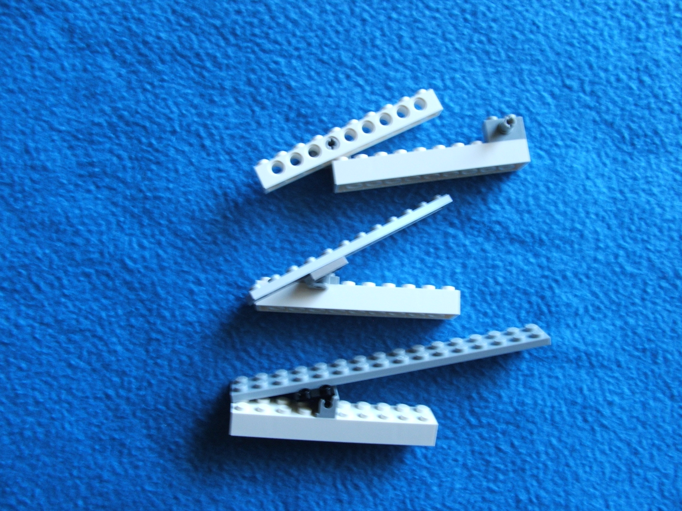
Whatever type of support system you use during the elevation run, the build will likely be vertical (standard build method). At the top (where the support meets the track) a hinge, ball/cup, or rocker elements can be used (as shown above) to compensate for the tilt needed at the angle of the track. Connect the track system to the support using any of the above elements, making sure they mesh well. If the elevation is constant for the entire run, then each support should have a similar connect method.
Another (in my opinion a BETTER) option is to use Technic elements for the elevation run. Technic beams can support the track and the elements which anchor to the support system float with use of the snap connectors.
Shown above are the elements with mock samples of how they allow angle connections.

Here we have two methods of connection shown from the bottom. This shows one way in which a connection could be made, there are many methods that could be used.
In BOTH (ball/cup at bottom
and Technic at top) examples
the track itself is supported
by a layer of elements to
stabilize it. The connection
to the vertical support is
anchored to the track support
rather than the track itself.
Both methods allow the track
angle to float
(angle
can change without having to
modify the connection) so you
do not need to calculate that
angle. This means you can
construct the vertical support
from the base and more easily
obtain a meshing connection
where the support meets the
track system.
These are EXAMPLES. In reality the pivoting elements would be more firmly attached to the other elements than they are as shown here. Keep in mind that the support system not only needs to hold the weight of the train but also needs to withstand vibration of the movement.
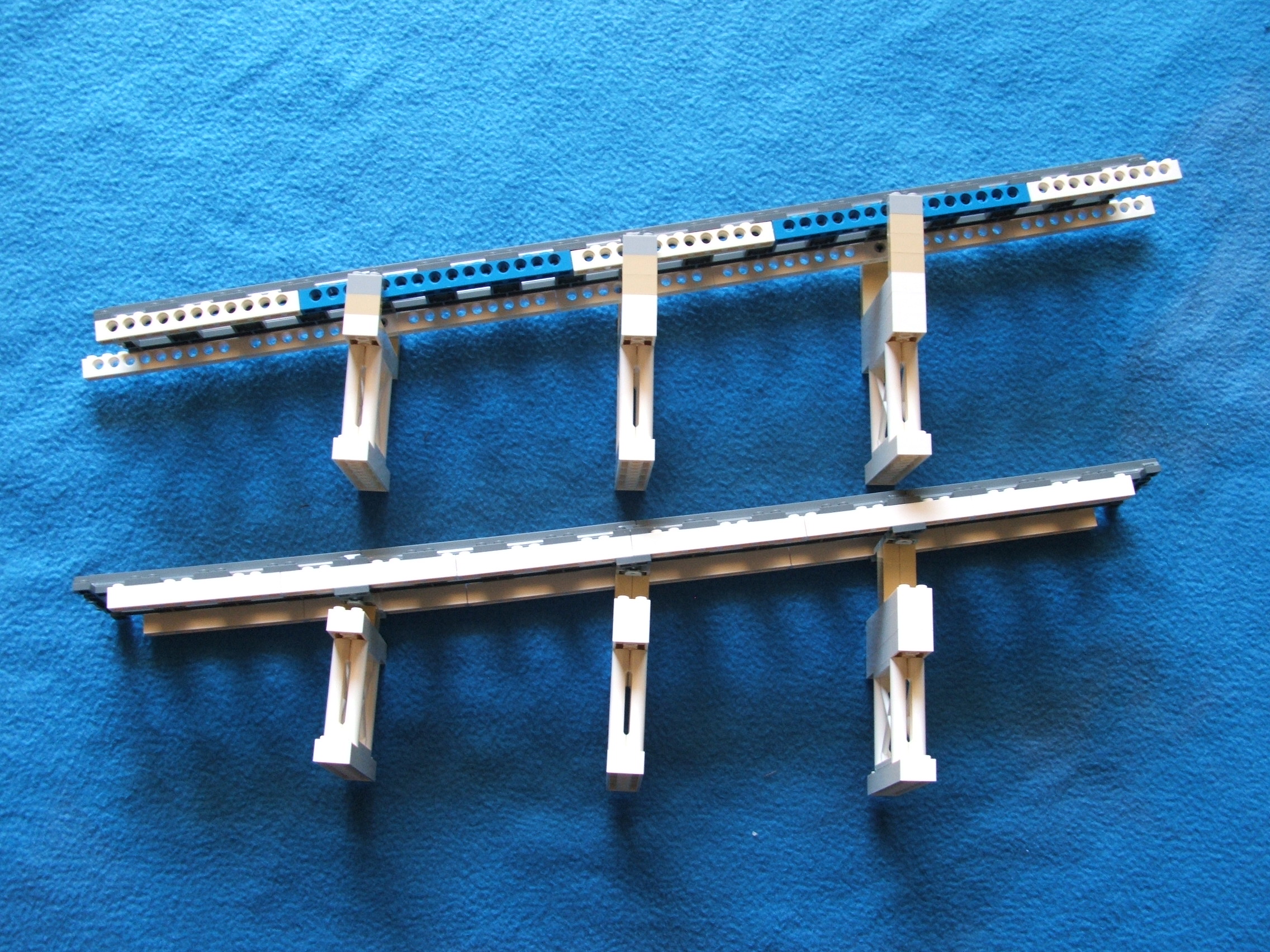
Shown here at 2 brick height per track (16 post) to more clearly show the angles.
This view demonstrates how the vertical support is converted to the angled track run. With some planning and fine tuning, meshing is possible when anchoring an elevation to a firm base structure.
Once you have the elevation and bridge structures figured out you still need to connect them to the rest of the layout. The most sensitive parts of an elevated system are the points where the elevation begins and ends at. This is because the track goes from level to angle at these points. There must be some way to deal with that.

Here we have a track run which
goes from level to 1 brick
height per straight track. The
track connection BEFORE the
first elevation brick is going
to want to bend. Notice the
plate placed UNDER that point.
It exists to help stabilize the
connection to transfer some of
that bend to the surrounding
connections. Sharing the
workload
reduces the bend
each connection will have and
improves the reliability of the
entire system.
Personally I would suggest that EVERY track connection prior to AND during an elevation or a bridge segment would have a 2x4 plate on top of it AND if possible (without interferring with the support system) below it. This will greatly improve the connections integrity.
It might take some time and it might take several attempts, but if you really want to have a bridge or tunnel in a layout the end result can be worth it.
Wrap up:
A LOT of people like trains! A LOT of people like Lego too! So it stands to reason that a lot of people will like a Lego train layout. And as it turns out, a LOT do!
In my opinion the best advice is to LEARN from other people but do not just copy their work. Each Lego creation should be as unique as the creator. Use your own style and perseption to bring life to your individual build. Even if you use the same train set, what you DO with it is what makes the difference.
Do whatever YOU want to do. If you are happy with a simple layout, then that works for you. There is no need to compete if the real goal is just personal enjoyment. You can always add on later as your desire and/or skills allow. Most creators are happy with their initial work but are always looking for ways to improve or expand it too.
HAPPY TRACKING!
Page last updated: February 09 2017 21:52:39.
Page visited: 3478
Terrys Place
Book, Motivation speaking, and Bullys
Facebook page
ICIC-ation YouTube channel
Vision and Driver/Bike/Pedestrian safety
Website design
Website programming and utilities:
© 2001-2025 Terry Erickson, All rights reserved.
Website layout and content:
© 2001-2025 Terry Erickson, All rights reserved.
Website hosting:

Proudly made in the USA!